Process modeling with Event-Driven Process Chains (EPCs) and BPMN Business Process Diagrams (BPDs)
| |
Copyright 2014 - 2026 by Josef L. Staud |
|
Author: Josef L. Staud |
|
Status: February 2026 |
|
This text contains a summary of my teaching materials on Event-Driven Process Chains (EPCs) and Business Process Diagrams of the BPMN, which I have used in university courses and other training seminars.
I continue to maintain and update these materials, as the topic and the associated methods remain of lasting relevance. |
|
Web and Book |
|
This text is published simultaneously as a printed version and as an online text. The bibliographic information is available at www.staud.info. The web version is slightly abridged; in addition, the print version contains a comprehensive index. |
|
Working with event-driven process chains inevitably results in large-scale diagrams. In addition to their inclusion in the text, these diagrams are published separately in a larger format and with higher graphical quality at the following addresses: |
|
https://www.staud.info/grafiken2020/GrafikenEPK.php
https://www.staud.info/grafiken2020/GrafikenBPMN.php |
|
Web Preparation |
|
These HTML/PHP pages were generated using a program I developed myself: WebGenerator (version 2026). It converts texts into HTML/PHP pages and is under continuous development. This "automated" generation makes it possible to immediately regenerate the HTML pages after every change to the text. Since it is not feasible to review all pages after each regeneration, it is quite possible that errors may occur on some more "remote" pages. I apologize for this and would appreciate any feedback or notifications (hs@staud.info). |
|
Copyright |
|
This text is protected by copyright. The rights arising from this protection, in particular the rights of translation, reprinting, public presentation, extraction of illustrations and tables, reproduction by other means, and storage in data-processing systems, are reserved, even in cases of partial use. Any reproduction of this text or parts thereof is permitted only within the limits of the statutory provisions of the Copyright Act of the Federal Republic of Germany of September 9, 1965, as amended. Such reproduction is, as a rule, subject to remuneration. Violations are subject to the penalties prescribed by the Copyright Act. |
|
Trademarks and Brand Protection |
|
All product names, trade names, trademarks, and brand names mentioned in this text are protected by trademark, brand, or patent law, or are registered trademarks of their respective owners. The appearance of such names and designations in this text - without explicit identification - does not imply that these names are free for general use under trademark or brand protection laws. |
|
Prof. Dr. Josef L. Staud |
|
staud@staud.info |
|
|
|
1 Introduction |
|
1.1 Preliminary Remarks |
|
The topic of process design and process optimization is of central importance for all companies and other organizations. It is a continuous task. However, process optimization requires that processes first be identified and described by means of process models. Only after this documentation has been carried out can weaknesses be identified and eliminated, and new approaches to process design - within the context of digitalization and automation - be incorporated. |
|
Significant changes have also occurred in the methods used over the past ten years. New methods have emerged, such as BPMN, while others that never truly gained acceptance in process modeling - such as UML activity diagrams - have largely disappeared. Event-driven Process Chains (EPCs), however, remain the ideal instrument for modeling processes in the context of an as-is analysis: they are simple, quick to learn, and nevertheless provide expressive process models, as will hopefully become clear in this text. One cannot reasonably expect more from a method. If, within the scope of requirements engineering, a more implementation-oriented modeling of processes is desired, other instruments should be chosen - for example, BPMN. |
Methods |
For presenting process examples, I use the terms concrete example and abstract example. Concrete examples illustrate a process (or a process segment) using specific, domain-related situations. They show how a process works in practice by referring to realistic tasks, documents, and decisions. Abstract examples, by contrast, use simplified and generic constructs that are independent of any specific application domain. Their purpose is to highlight the underlying syntactic modeling principles without being distracted by domain-specific details. |
Process Examples |
1.2 List of Abbreviations |
|
The following abbreviations are used throughout this text. They correspond to standard terminology in process modeling and related disciplines. Abbreviations that appear in Event-Driven Process Chains (EPCs) and Business Process Diagrams (BPDs) are explained within the respective process models. |
|
|
|
| Abbreviation |
Full Term / Meaning |
| AD |
Activity Diagram (UML) |
| AND |
Logical AND Operator |
| ARIS |
Architecture of Integrated Information Systems |
| B2C |
Business to Customer |
| BP |
Business Process |
| BPD |
Business Process Diagram |
| BPMN |
Business Process Modeling Notation (from Version 2.0: Business Process Model and Notation) |
| BPR |
Business Process Reengineering |
| eEPC |
Extended Event-Driven Process Chain |
| EPC |
(Basic) Event-Driven Process Chain |
| ERP |
Enterprise Resource Planning. An established term for integrated, process-oriented standard software. |
| IS |
Information System |
| IT |
Information Technology - originally meaning information technology in a narrow sense, but now commonly used as a collective term for an organization's entire data-processing infrastructure |
| OR |
Logical OR Operator |
| rE |
Resulting Events |
| RE |
Requirements Engineering |
| tE |
Triggering Events |
| XOR |
Logical Exclusive OR Operator |
| |
|
|
1.3 Structure of This Work |
|
This text is designed to introduce readers step by step to the modeling of business processes using Event-Driven Process Chains (EPCs) and Business Process Diagrams (BPDs) of BPMN. The structure follows this intent. |
|
- Chapter 2 presents, in general terms, how the literature defines business processes and process modeling.
|
|
Beginning with Chapter 3, the focus shifts to EPCs. |
|
- Chapter 3 introduces the foundational concepts as defined by the originators of the method (Scheer and his team).
- Chapter 4 deepens this understanding by presenting the basic patterns that can occur in EPCs.
- Chapter 5 provides an introduction to process modeling with EPCs through a commented example.
- Chapter 6 summarizes the syntactic rules, offers recommendations for the pragmatics of process modeling, and outlines several design guidelines.
|
|
Further discussions of EPCs and their modeling can be found in [Staud 2025]. This includes, in Chapter 8, numerous examples of EPCs with different modeling emphases. |
|
Beginning with Chapter 7, this text turns to BPMN. |
|
- Chapter 7 describes how the authors of BPMN conceptualize business processes.
- Chapter 8 presents introductory examples that illustrate the most important components and structural characteristics.
- Chapter 9 addresses the documentation of individual process steps.
- Chapter 10 explains how information and its processing are represented in BPDs.
- Chapter 11 describes how events are viewed and captured in BPMN.
- Chapter 12 is dedicated to the representation of sequence flows.
- Chapter 13 elaborates on gateways, the operators of BPMN, building on the discussions introduced earlier.
|
|
|
|
2 Business Processes and Process Modeling |
|
What are the "sequences" we call business processes and model using Event-Driven Process Chains or BPMN? How are they defined? What are their characteristics? How are they structured? And what challenges do the present and future pose for process modeling? These questions are addressed here so that we better understand the subject we are about to model - and thereby model it better. |
|
|
|
2.1 Definition |
|
Very simply put, business processes consist of goal-directed sequences of activities. In the literature, for activities performed by people or application programs within organizations to achieve set objectives, the terms task and operation are used. |
Goal-Directed Action |
Activities are generally defined as tasks, which can be viewed at different levels. The lowest level, so to speak, consists of elementary tasks - tasks that cannot be further decomposed, or that are not further decomposed at the level of description in question. Several such elementary tasks are then grouped into a task. We adopt the following definition, which also highlights the natural expectation of a result and the executability by humans or machines [Österle 1995, p. 45]. Here, software has been added: |
Elementary Tasks and Tasks |
A task is a business function with a determinable result. It is performed by people, software, and/or machines. |
Definition |
Tasks defined in this way can themselves be grouped - across multiple levels - up to the point where the entire corporate purpose is represented by a single task (e.g., "generate profit"). This is called aggregation, and it clarifies what plays an important role in the concrete modeling of business processes: |
|
The tasks to be performed within business processes can be considered at different levels of aggregation. In process modeling, tasks can therefore be split or combined. |
|
Subjective Level of Aggregation |
|
For process modeling, the consequence is that the level of aggregation at which tasks are considered is a subjective factor determined by the modelers or by the purpose of the modeling. Typically, a process model is more detailed where optimization is suspected to be necessary, and less detailed where the goal is primarily to represent the process as a whole (see the example in [Staud 2006, Section 6.2]). Frequently - deliberately - several different aggregation levels are modeled, e.g., to obtain overview representations. This leads to the vertical dimension of process modeling. |
|
Functions |
|
In both process discussions and concrete process modeling, the term function is used in a way that largely overlaps with the task concept but is more closely tied to the modeling environment. Mertens understands a function as an activity |
|
"...that aims at changing the state or condition of an object without reference to space and time. A function designation consists of two components: a verb (operation) and a noun (object) to which the verb refers (e.g., determine reorder point)." (translated by the author from the German original) [Mertens 2013, p. 41] |
|
In Event-Driven Process Chains, individual activities are called functions, regardless of the level of aggregation [Anmerkung] . |
|
By objects we mean business-relevant objects, i.e., business objects. This notion of object largely corresponds (often implicitly in the literature) to the general object concept of object-oriented theory. They are always carriers of information (e.g., an invoice) with attributes and behavior (or permissible changes). For example, invoices with attributes such as invoice number, date, and recipient, which can be paid or canceled. |
Business-Relevant Objects |
Operations |
|
The first step from individual tasks to a sequential series of tasks is made by defining operations. Following Bullinger/Fähnrich, operations are |
Sequential Task Sequences |
"Sequences of activities that are carried out to realize tasks." (translated by the author from the German original). [Bullinger amp; Fähnrich 1997, p. 19] |
|
They include organizational dimensions (e.g., positions) in their execution. Standardizable operations in companies are also referred to as workflows. They can be described on the basis of four categories: |
|
- Event flows control the activation of tasks depending on occurring events and thereby cause state changes in the system.
- Data or object flows model input information or objects required for task execution, and the use of results in subsequent tasks.
- Task performers represent positions in an organization and carry out tasks.
- Resources are materials or operating resources required for task execution; these may also include task performers.
|
|
A very similar view is offered by Scheer, who defines a business operation as follows: |
|
"An operation is a time-consuming occurrence that is triggered by a start event and completed by an end event. Depending on the operation's results, different control-flow branches, including backward jumps, may follow" (translated by the author from the German original) [Scheer 1998a, p. 20] |
Definition |
Operations, in turn, form business processes. This already states a good deal of what must be considered when modeling business processes: |
|
- The control flow, as it represents the event flows described above. Without knowledge of the correct sequences of the individual processes, or without the business rules that define them, there can be no business processes.
- The data used and the databases, since system state changes are the changes in data arising from service delivery.
- Data flows along business processes and within individual activities - especially across organizational boundaries today, based on the Internet and XML.
- Object flows, the objects involved in service delivery. These include business objects, which again brings us to data and databases, since business objects are, of course, typically stored in the organization's database today.
- Individual activities, based on tasks.
- Service providers as task performers, which today very often include application programs.
- The Organizational structure, represented through the concept of positions.
- The Materials and resources, required for service delivery.
|
|
All this - and a bit more - must be taken into account in process modeling if it is to be truly meaningful. |
|
Definition of Business Processes |
|
The author defines business processes in organizations - based on an analysis of definitions in the literature and on his own practical experience - as follows: |
|
A business process consists of a coherent, complete sequence of activities necessary to achieve an organizational objective. |
Definition |
These activities are performed by task performers within organizational units or by application programs, using the required production factors. The execution of business processes is supported by the organization's IT. |
|
Application programs have been added as task performers. This is indispensable in an era of increasing automation of business processes. |
|
Business processes thus perform the transformation of acquired production factors into products or services that are sold. In this context, business processes also describe the organization's value chain. |
|
From this we obtain key elements for modeling business processes: |
|
- Individual activities that make up the business process.
- The relationships between them, later called control flow.
- Embedding of the business process in the organization's overall activity by stating its objective.
- Task performers - the answer to "Who delivers the work?"
- Reference to automation of business processes (programs as task performers).
- Production factors and their consumption during process execution.
- IT support for process realization.
|
|
A method for modeling business processes must take all of this into account. |
|
The Concept of the Business Process |
|
In the early years of organizational theory, and well into the 1960s, optimization efforts focused on individual activities, their position holders, and the embedding of those activities within operational sequences. Later, the idea of the business process emerged. With the introduction of the business process concept, the perspective shifted. The primary focus now became longer, coherent sequences of activities required to accomplish a larger task - sometimes even a sequence of activities that, from the perspective of the organization under consideration, constitutes a complete and self-contained process. |
|
This remains the state of the art today. Most efforts to improve operational procedures in organizations in terms of effectiveness and efficiency begin with an analysis of the business processes and their optimization. |
|
Today (in early 2026), however, current AI techniques play an important role in this context. Which tasks can now be performed using these technologies? And how can they be integrated into business processes? |
|
Examples |
|
Below are several examples of business processes, aligned with the typical structure found in industrial enterprises: |
|
- Quotation creation (preparation of a quotation after an inquiry has been received)
- Order placement (placing an order with a supplier)
- Procurement (e.g., acquiring parts for production)
- Dunning process (e.g., regular reconciliation of open items and incoming payments)
|
|
And one business process that is typically quite long: |
|
- Order fulfillment or service delivery (from the moment the order arrives at the company to the delivery of the product to the customer)
|
|
Of course, there are also short business processes in the sense that they consist of only a few individual activities, for example: |
|
- Customer survey (e.g., as part of Customer Relationship Management (CRM))
- Personnel hiring
- Payment processing
- Approval of an investment
- Invoicing
|
|
2.2 Properties and Components |
|
There are, of course, many properties of business processes and process models worth considering (see the relevant literature
 ). We focus here on the most important - those that matter most for process modeling.
 |
|
2.2.1 Level of Detail in Process Modeling |
|
This property captures how detailed a business process is modeled. Were only a few milestones captured (as in the early years of process modeling in the 1970s)? Or all major sections at a coarse level? Or is the entire process modeled in detail - meaning that all tasks to be performed by participants are captured and modeled in detail? |
Comprehensive, Partial, or No Detailing |
Detailed modeling is a prerequisite for implementation in software; only then can models serve requirements management for software development - and, ultimately, full automation. |
|
However, detailed modeling is not always possible. The more standardized the relevant process sections are, the easier detailing becomes, because the sections are known. The less standardization (e.g., in creative areas such as strategy development, research, or development), the less detailed the modeling can be. Still, our daily experience with (almost) fully automated customer-facing processes on the internet and in companies shows that complexity is not, in itself, an obstacle to detailed modeling and software implementation. |
Detailed Modeling Only for Standardized
Processes |
In a process model, the level of detail is visible through the decomposition of activities. If they represent elementary activities, detailing is high. If many aggregations are used - possibly to the point where concrete actions are no longer representable - detailing is low. |
Recognizing the level of Detail |
2.2.2 IT Coverage |
|
This property captures the proportion of the process that is supported by IT - with an emphasis on support (as opposed to automation, i.e., complete execution by software). Today, application-software support for business processes is standard; what varies is the extent. Are only decision functions still not IT-supported, or are there sections that, despite being amenable to IT support, still lack it? |
Support by IT, Typically via ERP-Software |
Overall, IT coverage is now very high, particularly since the establishment of process-oriented integrated standard software (ERP). Most sections of business processes are now IT-supported. |
|
IT support can be captured by noting, for each activity, whether it is performed with software support and, if so, which application is used - in addition to who performs it. It can also be inferred from the information objects modeled: under IT coverage, these are part of an application's data store and (hopefully) marked as such. |
Capturing IT Support in the Model |
As noted above, IT coverage requires detailed modeling - e.g., in procurement, not merely procure parts, but identify eligible suppliers, request quotes, negotiate terms, formulate order, send order, etc., as in standard process modeling (see [Staud 2025, Section 12.1]). These elementary functions can then be mapped at a more detailed level to program constructs. |
Prerequisite: Detailed Modeling |
If such modeling prepares the development of integrated, process-oriented software, it is part of requirements engineering in the development project. |
|
2.2.3 Degree of Automation |
|
Another important property of processes or process sections is the degree of automation - the share of task performance completed without human intervention, solely by information technologies. In many areas, a high degree of automation is pursued; where flows are highly standardized and decision processes are simple, this goal has largely been achieved. A simple schema is fully automated / partially automated / not automated. |
Fully Automated, Partially Automated, Not
Automated |
In internet-based companies, fully automated business processes toward customers are now in place. The business model would not be conceivable otherwise. |
|
Automation presupposes the detailed modeling mentioned above and is feasible only for standardizable processes. Unlike mere support, decision procedures are encoded in software. For example, reordering for inventory is performed automatically; purchase recommendations are generated automatically (sometimes amusingly so); and handling of apparently non-paying customers is, to a significant extent, software-driven (see the "invoice" process example in [Staud 2019, Chapter 13]). |
Support vs. Automation |
In recent years, automation has been driven to a new level by AI - not only through text and speech technologies but also through software agents for process control and improved process mining, i.e., the digital recording and analysis of process executions. |
AI for Business Processes |
Automation is reflected by indicating the performers of activities. Where one would typically list an organizational unit, one now lists the application software - i.e., execution without (direct) human involvement. |
Capturing Automation in the Model |
Consider, for example, a typical B2C internet company: in key sections, besides the customer, only software is active (offering goods, making suggestions, recording orders, filling a (virtual) shopping cart, etc.). This extends deep into automatable sections of finance and logistics - and continues to expand. |
|
In requirements engineering for the corresponding software, after standard process modeling, the next, "lower" level of modeling must be chosen to be program-near. In this text, program-near process modeling refers to modeling that - e.g., within requirements engineering - directly prepares programming. See [Staud 2025, Section 12.5 and [Staud 2019] for the UML methods used at that stage. |
Program-Near Process Modeling |
2.2.4 Process Integration |
|
Another important characteristic of business processes is the degree of process integration. This refers to the end-to-end nature of a business process across different traditional organizational functions, such as procurement, purchasing, production, sales, accounting, and human resources. In addition - though only for a few years now - it also includes integration across organizational boundaries. |
|
This end-to-end integration is now generally achieved within organizations, while cross-organizational integration continues to be an area of ongoing development. |
|
An example of a lack of end-to-end integration - commonly referred to as media breaks - occurs when a business object cannot simply be passed from one process segment to the next, but must instead be re-entered. These points of discontinuity are called media breaks. They are not necessarily apparent in process modeling, because the same business object may simply appear again in the subsequent process segment. This must be made explicit, among other things, through modeling the transfer of information (see [Staud 2025, Section 7.1]). |
Media Breaks |
Further examples of media breaks include: |
|
- Output of information in one software system followed by manual input into another
- Incoming information (e.g., related to order receipt) that must be processed in order to be transferred into the organization's own application software
- Information required for a forecasting calculation that cannot be provided in the form in which it is needed
|
|
At its core, the situation is this: if the same information that has already been captured must be captured again, there is a deficiency in process integration. |
|
This property can be captured by recording the information objects associated with each activity precisely. For example, for invoice receipt: first the invoice at the central office handling incoming mail; then the invoice in Finance. A transfer was needed between these points. Ideally, the invoice would be stored in the organization-wide integrated database at the first activity and accessed at the second. With media breaks, this fails - the invoice must be re-entered, scanned, etc. This constitutes a media break and should be modeled explicitly. |
Identifying Media Breaks |
When exchanging information objects between organizations, we speak of semantic process integration if, in addition to the absence of media breaks, the semantics of the information object (invoice, delivery note, coordination information, ...) is recognized by the recipient. Many companies are working toward this in B2B [Anmerkung] contexts. |
Semantic Process Integration |
2.2.5 Data Integration |
|
Another important characteristic is the degree of data integration, that is, the integration of the data repositories required for the individual activities of a business process. This aspect is of great importance, since non-integrated data repositories lead to friction losses. In concrete terms, this can mean the following: data related to a specific area, task, or business process |
"Friction Losses" Due to Lack of Integration |
- ... exist in different digital or even non-digital data repositories and are therefore fragmented,
- ... exist in different data repositories and are inconsistent (e.g., differing product data, addresses, etc.).
|
|
Beyond database incompetence or sloppiness, a common source of such deficits is organizational mergers - which also merge IT and databases. Both are complex and often not comprehensively solved, or only belatedly. |
Source |
How can such deficits be detected in process modeling? By precisely recording the information produced or used by each activity. If modeling is sufficiently detailed and accurate, fragmentation will be revealed. Contradictory data stores, however, cannot be resolved within process modeling; they require additional effort, including a close look at database structures. |
Detecting Insufficient Data Integration |
Here, we reach one of the limits of process modeling (see [Staud 2025, Section 10.2]). Data integration requires a database-oriented analysis of the data repositories in order to take a step toward an integrated enterprise database. |
|
2.3 Objectives of Process Modeling |
|
The first objective of any business-process modeling effort is fact-finding - determining which business processes run in which form. This may directly yield documentation (e.g., for ISO 9000 certification) or descriptions used to prepare the introduction of ERP software. In the latter case, as-is analyses compare the ERP software's pre-defined processes with the organization's documented processes: |
As-Is Analysis |
An as-is analysis is the documentation of an existing process with all its characteristics and deficits. |
Definition |
The second major objective is business-process optimization - eliminating weaknesses identified during process capture. Examples include: |
Optimization |
- Lack of data integration (data islands)
- Lack of process integration (organizational breaks)
- Excessive transport times for process objects (documents, invoices, CAD drawings)
- Excessive waiting and queue times for process objects
- Excessive processing time
- Excessive setup and throughput times
- Redundant activities
- Excessive complexity (e.g., high planning and administrative overhead)
- Insufficient process mindset (poor understanding of upstream/downstream sections)
- Excessively long communication and decision paths
- Excessive total process costs
- Insufficient transparency (which can hinder process change)
- Inadequate process accountability
- Fragmented responsibilities
|
|
Some deficits become apparent immediately during modeling; others only when focus is set according to objectives. These objectives strongly shape the concrete design of the modeling. Depending on the suspected deficit, the emphasis will differ. In [Staud 2006, Section 6.2], a business process is presented where this becomes very clear: the entire order fulfillment is modeled, but the focus was on improving the creation of required CAD documents. Therefore, modeling is very detailed in sections addressing that topic, while in other sections - where the goal was merely to bridge gaps to allow modeling of the entire process - aggregation is coarser, even superficial. |
Process Modeling with a Specific Objective |
Further objectives - under the heading "Use Cases for Process Models" - are listed in [Becker, Kugeler and Rosemann 2012, pp. 199f]: |
Use Cases for Process Models |
- Organizational documentation, for example, for up-to-date descriptions of business processes.
- Process-oriented reorganization, whether revolutionary or evolutionary.
- Continuous process management, long-term planning, execution, and control of processes.
- Certification according to DIN ISO 9000 ff., possible only with documented models.
- Benchmarking, comparing one's own business processes with those of other organizations.
- Knowledge management, aimed at creating transparency regarding the organizational resource of knowledge.
- Selection of ERP software, by comparing the organization's own process model with that of the ERP vendor.
- Model-based customizing, parameterization of the software.
- Software development, as part of the requirements specification.
- Workflow management, using process models as the basis for creating workflow models.
- Simulation, analyzing system behavior over time with the goal of process optimization.
|
|
Customer Orientation as the Goal of Process Modeling |
|
Naturally, the central objective of any process optimization effort is to enhance value creation. The path toward this objective, however, leads - as the literature consistently agrees - through a strong orientation toward the customer. See [Schmelzer and Sesselmann 2013, Section 2.2]. |
|
2.4 Challenges for Process Modeling |
|
What are the challenges in process modeling? The most important can be summarized under the keywords level of detail, automation, and the use of AI. |
|
2.4.1 Level of Detail |
|
This was already discussed among the properties of business processes, but it is also a trend with direct impact on process modeling: the increasingly detailed IT support of business processes. Since the beginning of the data-processing era, organizations have tended to extend and deepen IT support (see [Staud 2006, Chapter 2]). Today, almost every task in an organization is supported by an application system. This has only been possible through increasingly detailed process modeling, which, as we know, now covers almost every work step. |
Ever-More Detailed Process Models |
This trend requires adapted process modeling. The classic as-is analysis must be complemented by program-near process modeling (see [Staud 2025, Section 12.5]). |
|
The term level of detail refers to the degree of refinement with which a business process is represented in a model. A high level of detail means that all individual tasks and decision points are explicitly modeled, while a low level of detail indicates a more aggregated representation of activities. |
Definition |
The appropriate level of detail depends on the modeling objective: detailed models are required for implementation or automation, whereas less detailed models may suffice for documentation or overview purposes. |
|
2.4.2 Automation - Opportunities and Limitations |
|
The property of the degree of automation discussed above is also an expression of a broader trend in the development of IT in general and of process modeling in particular. An automated business process is one that is realized by software without direct human involvement. This is nothing new in technical domains - automated processes have long been present in technical systems (ATMs, for example). |
|
In the implementation of business processes in software, however, this was not the case until relatively recently. It has been implemented in a truly comprehensive manner primarily by companies that operate on the internet or with the help of the internet. All business processes that involve customers are realized through application software, as are subsequent processes in logistics and finance. |
|
In these areas, however, automation is not comprehensive but rather partially supported by humans. One need only think of collection agencies or of important company-side decisions that must be made by people. Work in the large warehouses of online retailers is also still partially human-supported. |
|
A similar situation can be observed in other organizations that do not primarily operate on the internet. The application software used there, based on very detailed modeling of business processes, is partly automated and partly not. This is why the proportion of automated segments could be introduced above as a relevant property. |
Partly automated, partly not. |
This should already be clear, but it is worth emphasizing once again: automation requires implementation-oriented process modeling, in addition to as-is analysis. With this, process modeling has definitively entered the domain of requirements engineering for software development. See [Staud 2025, Sections 12.3 and 12.5]. |
Prerequisites |
2.4.3 Use of Artificial Intelligence |
|
This section is under preparation. |
|
|
|
3 Fundamentals of Event-Driven Process Chains |
|
Preliminary note: For all references to [Staud 2025], the following applies: A short version of this book is available on my website at https://www.staud.info/epk2/ep_t_1.php |
|
|
|
3.1 Introduction |
|
Event-Driven Process Chains (EPCs) describe business processes, their activities (referred to as functions), the events that control them, the actors involved (referred to as organizational units), and the information that is used or generated (referred to as information objects). They describe all possible realizations of a process by means of branching and merging constructs (operators, connectors), thereby specifying the so-called control flow of the business process. |
The EPC Method |
They are the tool of choice for the analysis and description of business processes. This applies in particular to as-is analyses of business processes and to the representation of optimized processes (to-be modeling). Only when modeling aims at a higher level of detail - for example, in preparation for the implementation of process-oriented software - are other modeling methods more suitable (see Sections 12.2 and 12.5 in [Staud 2025]). |
As-Is Analysis and To-Be Modeling |
This method and the associated graphical modeling technique (notation) for business processes were developed by Scheer and his colleagues as part of the ARIS concept (see [Keller, Nüttgens, and Scheer 1992], [Scheer 1997]). For a brief overview, see [Staud 2025, Section 13.1]). |
ARIS
Architecture of Integrated Information Systems |
Event-Driven Process Chains are a semi-formal method. They do not meet the requirements - as will also become apparent later - that must be fulfilled by formal methods or languages. Rosemann expresses a similar view in his contribution in [Mertens et al. 1997, p. 334], where he distinguishes between |
Informal - Semi-Formal - Formal |
- informal methods, for example textual descriptions,
- semi-formal methods, for example Event-Driven Process Chains, and
- formal methods, such as predicate logic.
|
|
The requirements for such a method listed there - representation of control flow, modeling of concurrency, conditional branching, and loops, depiction of data flow, as well as the specification of the involved organizational units and information systems - are readily fulfilled by Event-Driven Process Chains (EPCs). |
|
Despite the fact that this notation is not fully formal, the term syntax is also used here to refer to the rules governing the correct construction of Event-Driven Process Chains. |
Syntax |
3.2 Elements |
|
In [Scheer 1997], during the derivation of the ARIS concept, the elements of business processes were identified. In the concrete formulation of the EPC method, he summarizes them as follows: |
Four Elements plus Control Flow |
- Functions
- Events
- Organizational units, and
- Information objects
|
|
In addition, control flow and - to a limited extent - data flow are taken into account. |
|
3.3 Functions |
|
All activities that must be carried out within a business process are captured as functions in an EPC as part of process modeling. That is, the overall task of the business process (e.g., prepare a cost calculation) is decomposed into individual subtasks, with more or less detail. The decision regarding the scope of elementary activities represented by an individual function is left to the modelers. Consequently, the subjective factor of modeling discussed in [Staud 2025, Section 2.2.1] remains applicable. |
What Is Performed? |
For human actors, functions describe their operational activities; for an information system, they represent something like a transaction or a business function module. |
|
In this modeling approach, the time consumption of functions is not quantified. That is, no indication is given of how much time (maximum or minimum) is required to perform the activities captured by a function. Nevertheless, the temporal dimension of a business process is integrated into this modeling approach in multiple ways. See Sections 6.3 and 6.4 in [Staud 2025]. |
Time Consumption |
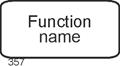
The graphical representation of functions is a rectangle with rounded corners and a label centered within the rectangle. See the following figure. |
|
|
|
Figure 3.3-1: Functions - Graphical Representation |
|
The naming of functions should be done in such a way that the activity is clearly recognizable, preferably by combining a noun and a verb. Examples include: |
|
- Check feasibility or Feasibility check
- Prepare a cost calculation
- Reject an order
|
|
3.4 Events |
|
In this context, events are understood to be events that are relevant from a business perspective. These events influence and control operational processes within an organization in one way or another. Examples include: |
|
- Order received
- Quotation is valid
- Order confirmation sent
- Transfer prepared
- Customer inquiry rejected
- Customer is new (as the result of an appropriate check)
|
|
Events should be named exactly as in these examples, that is, as propositional statements. This clearly conveys their event character. |
|
For defining events in process modeling, we can rely on the everyday notion of an event, with the additional requirement that the events must be business-relevant and meaningful for the business process under consideration. |
|
This definition becomes more specific when considering that process modeling assumes a close relationship between functions and events. For example, the execution of a function always leads to an event (such as "completed"), or to several events. |
Function - Event - � |
Events are related to a specific point in time, although this point is usually not explicitly specified. In common representations, it is determined only by embedding the event into a chain of activities (functions) and events - that is, into a branch of the control flow. In other words, events trigger functions and are the result of functions. This is the reason why Scheer writes: |
|
"An event can be defined as the occurrence of an object or a change in a specific attribute value." [Scheer 1998, p. 49], translated by the author. |
|
Here, Scheer uses the term objects to refer, for example, to products. Events in this sense can arise from preceding activities as descriptions of possible outcomes, but they can also refer to subsequent processing steps or - seemingly out of nowhere - originate externally (IT system was hacked, Order received). |
|
The set of all events that are possible within an organization and its environment is referred to as the organization's event space. |
Event Space |
An event is always also a statement that must be made somehow and by someone. Actions precede it, and in most cases further actions follow it. These are captured here using the concept of functions introduced above. |
|
Events, like functions, can be aggregated or decomposed. Consider the deliberately high-level event "The company has not generated any profits." This could just as well be described by "events" such as "Sales decreased by x%", "Costs amounted to y", and so on. In principle, the level of aggregation of events should be aligned with that of the functions. |
Aggregation of Events |
Two events of every business process deserve special attention: the start event and the end event (or final event). A business process begins with the start event - prior to this, there are no actions with respect to the individual business process - and it concludes with the end event. In principle, a process may also have multiple start events and multiple end events. |
Start and End |
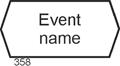
The graphical representation of events in Event-Driven Process Chains is a horizontally stretched hexagon with the name of the event centered inside the shape. |
|
|
|
Figure 3.4-1:Events - Graphical Representation |
|
3.5 Organizational Units |
|
Organizational units are used to specify who performs the task captured by a function. This may be a classical organizational unit (department, position, etc.) or the application software that realizes the function in an automated manner. Application software may be conventionally programmed, such as typical ERP software, or implemented using modern AI techniques. |
Who Performs the Task? |
When functions are performed by humans, organizational units are often defined at a very fine level of granularity today - especially when staffing levels are already low and or when the organization is moving away from a traditional hierarchical structure. In such cases, it may even be appropriate to model organizational units at the level of individual positions in order to obtain sufficient explanatory power for the analysis of weaknesses. |
|
Examples of (classical) organizational units in an industrial enterprise include Sales, Human Resources, Production, and Information Services. |
|
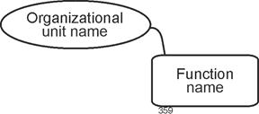
The graphical representation of organizational units in Event-Driven Process Chains is an ellipse with the label centered inside. Organizational units are always connected to the function they perform by a non-directional line. |
|
|
|
Figure 3.5-1: Organizational Units and Their Connection to Functions |
|
Design Rule: Organizational Units |
|
In many projects, it is common practice to omit organizational units at a function if they are the same as for the preceding function. If no organizational unit is shown for a function, one must therefore trace upstream to the last occurrence. |
|
[Staud 2025, Section 7.6] discusses several issues related to the specification of organizational units. |
|
3.6 Information Objects |
|
No organization can operate without data repositories that model the organization itself, its business objects, and its informational environment, either in full or in part. These data repositories are therefore of great importance for the execution of business processes. In Event-Driven Process Chains (EPCs), this is reflected in the specification of the information that is retrieved (received) and used, or that is created, at each function. This may include customer data, details from a previously prepared quotation, current market prices, or any other information that is relevant for a particular segment of the business process. |
Which Information Is Required by a Function?
Which Information Is Created? |
In the EPC method, such data are referred to as information objects (IO) and are associated with the function for which they are required. For example, the following information objects may be assigned to a function Order Processing: |
IO Supporting Business Processes |
- information about customers
- information about the quotation
- information about materials
- information about terms and conditions
- information about the customer order
- information about required parts, and so on.
|
|
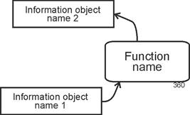
Information objects are graphically represented as rectangles with the name centered inside. Each information object is connected to a function. In the relationship between information objects and functions, an arrowhead is used to distinguish whether the information flows into the function - that is, is required for task execution - or whether it is created by the function. The arrowhead thus indicates the direction of the information flow. |
Rectangle with Arrowed Line |
|
|
Figure 3.6-1: Information Objects and Their Connection to Functions |
|
As will be seen below, data flows (in the sense of data flow diagrams) are captured in this way only if this part of the modeling is carried out very carefully, which is often not the case in practice. |
|
Information objects do not have to consist solely of data from databases. In principle, any information on any type of information medium can be taken into account. Explicitly indicating non-electronic media (in the context of an as-is analysis) can even provide an initial indication of opportunities for business process optimization. |
Information Media of All Kinds |
In general, information objects also provide indications of the degree of automation of the business process under consideration. In non-automated or only partially automated segments, information objects are often (though not always) non-digital. |
IO and Automation |
3.7 Control Flow |
|
The construct of control flow was already introduced in the introduction to this chapter. It can now be specified more precisely. The possible sequences of events and functions within a business process, starting with start events and ending with end events, are referred to as the control flow. |
The Invisible Organizing Hand |
A single concrete execution of a process is referred to as an instance. Accordingly, the control flow can be understood as the set of all possible instances of a business process. Further details on instances, and especially examples, can be found in Section 5.5. |
Instances of a Business Process |
A note for readers familiar with object-oriented theory: there is a certain parallel between the concepts of business process model and business process instance and the concepts of class and instance. The former denotes the abstract, general representation and specifies the overall structure, while the latter refers to a concrete manifestation. Beyond this analogy, however, the comparison does not extend further. |
|
Thus, control flow refers to all possible executions of a business process, including all branches, as required by the semantics of the business process. This is where business rules are expressed, as well as common sense (for example, an offer must be prepared before it can be sent). |
|
Control flow is also related to authority. Internal organizational procedures are, naturally, shaped by this as well. At certain points in a business process, decision situations arise that must be handled by the process actors. Such authority typically does not exist with respect to an organization's external partners. For this reason, the originators of the BPMN method allow only message flows for interactions "to the outside", and not control flows - or, as they are referred to in BPMN, sequence flows. |
Authority |
Events and functions that follow one another in the control flow are connected by arrowed lines. More details on this are provided in the following chapters. These arrowed lines are often also referred to as edges, drawing on terminology from graph theory. Multiple such edges, together with their associated events and functions, form a control-flow branch. Such a branch can extend from a start event to an end event. |
Edges and Control-Flow Branches |
Business processes, and thus Event-Driven Process Chains, have a direction - from the start event to the end event - which is why it is also possible to speak of upstream (back toward the start event) and downstream (toward the end event). |
upstream and downstream |
3.8 Operators |
|
The control flow of a business process does not consist solely of simple sequences of events and functions, but also includes branching of control-flow paths and their merging. This occurs, for example, when several activities must be carried out "in parallel" in order to achieve a goal, or when alternatives exist - either one activity or another leads to the goal. The same applies to events. In some cases, alternative events may trigger the same activity, or multiple events together may constitute the condition for the start of an activity. |
Operators, Connectors |
To represent these structural characteristics of business processes and Event-Driven Process Chains (EPCs), operators (sometimes also referred to as connectors) are required. |
|
For modeling business processes with EPCs, three operators are sufficient. Their names and graphical symbols are as follows: |
|
- AND:

- OR:

- Exclusive OR (XOR) - also referred to as XOR:

|
|
These are n-ary logical operators, meaning that at least two elements are always connected. The following rule applies: either events are connected to events or functions are connected to functions. |
|
Note |
|
Operators can only connect events with events and functions with functions - not events with functions. |
|
Connected Events |
|
Numerous examples of elementary connections are presented in Chapter 4. |
|
For events, the operators have the following meanings: |
|
- AND: all connected events must occur before the control flow continues
- OR: at least one of the connected events must occur before the control flow continues
- XOR: exactly one of the connected events must occur before the control flow continues
|
|
Connected Functions |
|
For functions, the operators have the following meanings: |
|
- AND: all connected functions must be performed before the control flow continues
- OR: at least one of the connected functions must be performed before the control flow continues
- XOR: exactly one of the connected functions must be performed before the control flow continues
|
|
A more precise determination of the meaning of the operators depends on their position within the control flow - for example, on whether the connected events occur before or after a function. See the connection examples in Chapter 4. |
|
In graphical representations of Event-Driven Process Chains, it is usually assumed, for reasons of clarity, that the control flow is arranged from top to bottom. For this reason, operators are placed in the graphical notation as a circle divided into two halves, for example as follows: |
|

|
|
Where an operator is present, there is more than one edge. If no operator is present, there is only a single edge. If there is more than one edge both above and below, operators must be present on both sides. Two examples are shown below: |
|

|
|
The upper half of the operator symbol indicates how the incoming control-flow paths - represented by events or functions - are connected. The lower half does the same for the outgoing edges. |
|
Syntax Rule |
|
Branching and merging of control-flow paths may only be performed using the three operators AND, OR, and XOR. |
|
Two additional terms are used in connection with operators: splitters and joiners. If one control-flow path arrives and several depart, the operator is referred to as a splitter. Conversely, if several paths arrive and only one departs, the operator is a joiner. |
Splitters and Joiners |
3.9 Temporal Dimension |
|
The sequence of functions within a control-flow branch also expresses a temporal dimension. For example, the function Check inventory level can only be started after the event Inquiry received has occurred; the function Reject customer can only be executed if the event Inventory insufficient has occurred beforehand, and so on. In other words, a function is only started once the preceding one has been completed. |
Temporal Dimension of a Business Process or an
EPC |
Thus, a first fundamental temporal ordering is established in every Event-Driven Process Chain by arranging functions - separated by events - sequentially. This determines their order. However, this specification is not an absolute one that includes a quantified duration, but rather a relative one in relation to the other functions. |
Not Absolute, Only Relative |
In Event-Driven Process Chains, the time consumption of a function - for example, a specification such as this function must be completed within one day - is generally not captured. An exception arises for functions that express waiting for a response from another party (waiting functions). In such cases, it is entirely conceivable to incorporate an event into the EPC that signals the expiration of time. For example, one outcome of a waiting function could be an event such as Time has expired or Two weeks have passed. |
Time Consumption |
How to "Preserve" Information About Time |
|
Process modeling with Event-Driven Process Chains does not include messages, information channels, or similar elements that could establish a communication network with storage capabilities. The basic philosophy is as follows: information is written to the integrated enterprise database at the time it is created and is later read again in the process when needed. This also corresponds to the implementation found in ERP software, provided that it does not include workflow components, which, by their nature, are based on direct information exchange. |
Writing to and Reading from the Database |
More system-oriented modeling approaches, such as the dynamic components of UML (sequences, activities, state machines, use cases, etc.), partly take different approaches. In these, the concept of message exchange between system elements does exist. The BPMN method also supports message exchange between acting entities, and even includes a broadcast signal, that is, a message sent to all other components. |
|
3.10 Design of EPC Diagrams |
|
The following rules are applied in this text to the design of EPCs and to the presentation of extensive figures: |
|
- Consistent organizational units. If the organizational units remain the same for a subsequent function as for the preceding one, they are not shown. This serves to improve readability. If no organizational unit is indicated for a function, it is therefore necessary to look upstream to the first function for which such an assignment is shown. This principle is not applied consistently throughout this text, in order to increase the explanatory power of the respective EPCs. Consequently, if a situation becomes unclear or if the last function with an assigned organizational unit lies far upstream, organizational units are nevertheless added.
- Transport of information. For information objects that are merely transported and neither created nor read, no arrowheads are shown in the Event-Driven Process Chains. This is a deliberate decision by the author intended to make information transport activities easier to identify. See also [Staud 2025, Section 7.1].
- Function - function - function - ... In many organizations, it is common practice to omit events in a simple (non-branching) sequence of events and functions. This approach is not adopted here - since the primary focus is on conveying knowledge of the EPC method and the Event-Driven Process Chains presented here are not as large as those typically found in organizational projects.
|
|
|
|
4 Basic Patterns |
|
|
|
4.1 Possible Arrangements |
|
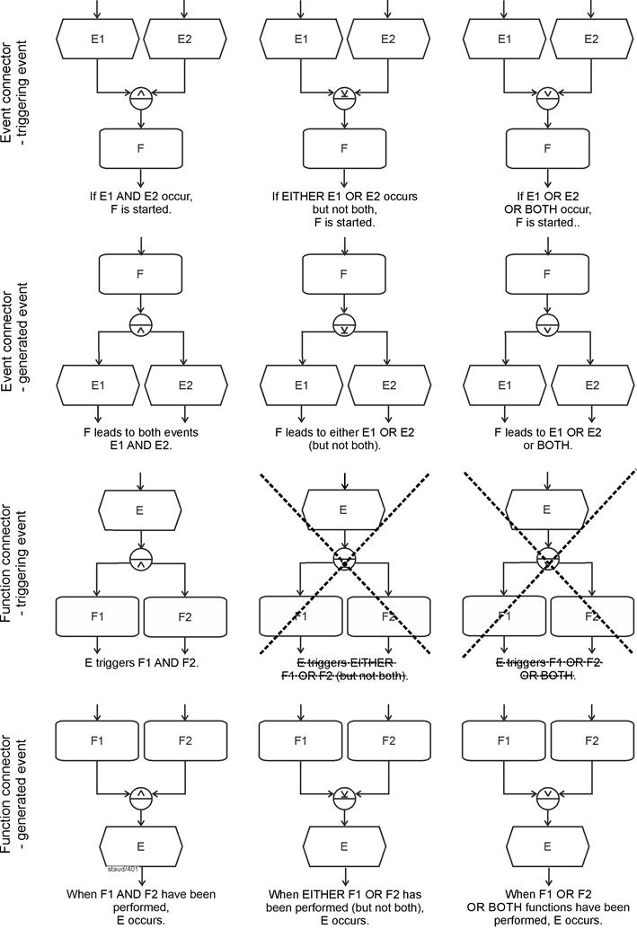
This section examines the ways in which events (E) and functions (F) can follow one another in the control flow when they are connected by operators. For each of the three operators, we distinguish, first, whether events or functions are being connected, and second, whether the events in the respective EPC fragment precede or follow the functions. This yields the twelve variants shown in the following figure. |
All Possible Arrangements of E and F in the
Control Flow |
The figure presents the possible combinations in an abstract form, using labels such as E1, E2, ... for events and F1, F2, ... for functions. In addition, only two events or two functions are shown for each operator connection. Content-related example fragments follow in the subsequent sections. |
|
To improve readability, the control flow is always arranged from top to bottom, with one side of the operator symbol at the top and the other at the bottom. |
|
For arrangements in which events come first and functions follow, we refer to the events as triggering events (tE). See rows 1 and 3 in the following figure. The meaning of this term becomes clearer in the examples below, where it can be seen that in certain arrangements the events effectively serve as triggers for the functions that follow them. |
Triggering Events |
In the opposite case, where events follow functions, we refer to them as resulting events (rE). In such cases, the events are, so to speak, produced by the execution of the function. See rows 2 and 4 in the following figure. The examples below will also help clarify this meaning. |
Definition: Resulting Events |
The crossed-out connections in the figure are not permitted; more on this below. |
|
Note: The EPC fragments shown here are typically excerpts from larger EPCs. The arrowheads at the top and bottom indicate how these fragments connect to the surrounding model context. |
|
|
|
Figure 4.1-1: Possible Connections of Events and Functions Using Operators |
|
E: Event, F: Function |
|
In the following, the arrangements shown in the table above are discussed sequentially, from top to bottom and from left to right, each accompanied by at least one meaningful example. |
|
4.2 Event Connections with Triggering Events |
|
Event connections with triggering events always mean that events act as conditions for the function to be executed next (there may also be several functions). |
Events as Conditions |
4.2.1 AND |
|
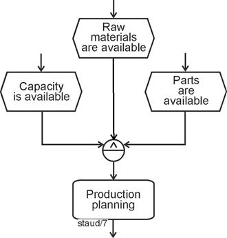
If triggering events are connected using the AND operator, all of them must have occurred before the control flow continues beyond the operator. In such a situation, the events have the character of joint conditions for starting the function: the function is only started once all events have occurred. |
Joint Conditions |
In the following example, the situation after an order has been received is considered. Production planning is only started once capacity is available and the necessary raw materials and resources are present. |
|
|
|
Figure 4.2-1: Event Connections / Triggering Events / AND |
|
In this way, rules and regulations that apply to the respective process can be incorporated into the model. |
|
4.2.2 XOR |
|
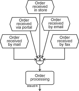
When triggering events are connected using an exclusive OR (see the following figure), they represent alternative events for which exactly one must occur for the control flow to continue and for the subsequent function to be started. The triggering events thus represent conditions of which exactly one must be fulfilled for the business process to proceed. |
Alternative Conditions |
In the following example, orders are considered. It is assumed that these may have been received by letter, via an online portal, in a physical store, by email, or by fax. This is modeled by start events that are, by their nature, alternative - which corresponds to the logic of the exclusive OR. Thus, order processing is started only if one of these events has previously occurred. |
|
|
|
Figure 4.2-2: Event Connections / Triggering Events / XOR |
|
4.2.3 OR |
|
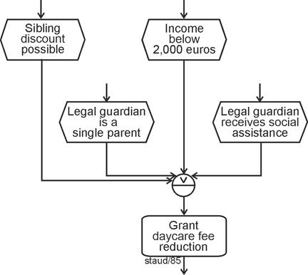
Event connections using the logical OR mean that at least one of the parallel events must occur for the subsequent function to be started. As the wording already indicates, several or even all events may occur. |
At Least One Event Must Occur |
The following example concerns the question of whether parents may be granted a fee reduction when their child attends a daycare center. The criteria for this were formulated as events. A reduction may be granted if ... |
|
- ... a sibling already attends the daycare center (sibling discount).
- ... the income of the legal guardians is below USD 2,000.
- ... the legal guardian is a single parent.
- ... the legal guardian receives social welfare benefits.
|
|
If at least one of these events occurs - that is, if at least one criterion is fulfilled - the reduction may be granted. The OR operator can therefore be used. |
|
This example is fictitious. In practice, the actual set of rules is likely to be considerably more complex. |
|
|
|
Figure 4.2-3: Event Connections / Triggering Events / OR - Example 1 |
|
In this example, the question arises as to why the individual events (criteria) are specified at all. Would it not suffice to use a single event such as Reason for reduction applies following a function that checks this condition? This would certainly be possible. However, it is often desirable to document the various alternatives explicitly in the Event-Driven Process Chain. In such cases, the modeling approach shown above is appropriate. |
Possible Aggregation |
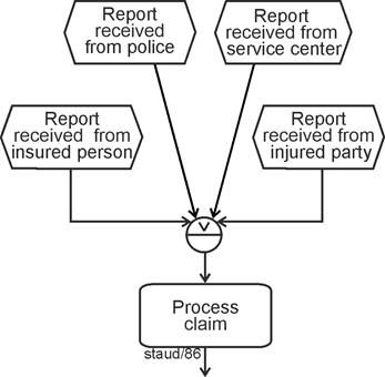
The following second example describes a similar situation in an insurance company. A claim may be reported by the policyholder, the injured party, a service center, or in rare cases even by the police. It may also be reported by several of these "reporting parties" - for example, by both the insurer and the injured party. Here as well, the logical OR is therefore the appropriate operator. |
|
|
|
Figure 4.2-4: Event Connections / Triggering Events / OR - Example 2 |
|
Here too, the OR condition is fulfilled. For the concrete business process, this means in practical terms that potential multiple notifications (the same claim being reported several times) must be handled appropriately. |
|
As already noted above, events connected by OR can always be aggregated. However, when events are modeled in a detailed manner, the intention is to document the possible alternatives and their combinations. This information may also be required elsewhere in the Event-Driven Process Chain. For example, in the fragment concerning the granting of a fee reduction, it may be useful in certain cases to know which criteria were the reason for the reduction, even if this information is not strictly necessary for the further process flow. In such a case, however, this information storage would need to be modeled explicitly using information objects. |
Aggregation or Detailing |
4.3 Event connector with generated events |
|
In this configuration, the events signal the execution of a function (or several functions); they indicate partial tasks or possible results. |
|
4.3.1 AND |
|
With the logical AND, the subsequent events represent partial tasks that result from the execution of the function. These are intermediate results that are considered sufficiently important to be explicitly represented in the model. Formally speaking, all subsequent events must occur (all partial tasks must be completed) before the business process can continue. |
Partial tasks with AND |
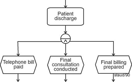
The following example is taken from a real-world hospital context and addresses the process of discharging patients after an inpatient stay. For the sake of simplicity, it is assumed that this includes paying the telephone bill, conducting a final consultation, and preparing the final billing. |
|
|
|
Figure 4.3-1: Event Connections / Generated Events / AND |
|
In this context, the AND operator does not indicate parallelism (of subtasks), but merely that all of them must be completed before the next function can be started. Subtasks can also be modeled in other ways. Triggering several functions after an event, as shown in the introductory example, can likewise be interpreted as triggering subtasks. See [Staud 2025, Section 6.2] for a more detailed discussion of subtasks. |
No Parallelism in the Technical Sense |
4.3.2 XOR |
|
With the exclusive OR, event connections with generated events indicate that the events represent possible alternative outcomes of the preceding function. That is, exactly one of the events must occur for the control flow to continue. |
Capturing Alternative Outcomes |
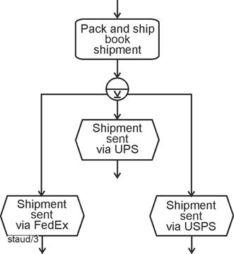
The following example describes - in a publishing company - the process that leads to the shipment of books. After a shipment has been prepared for dispatch, it is sent using one of the transport companies. Naturally, only one can be selected, since the shipment can only be sent once. The events therefore represent possible alternative outcomes. |
|
|
|
Figure 4.3-2: Event Connections / Generated Events / XOR |
|
Shipping providers:
UPS (United Parcel Service, Inc.) - US-based parcel and logistics company
FedEx (Federal Express Corporation) - US-based global express and logistics provider
USPS (United States Postal Service) - US public postal service offering mail and parcel delivery
[ChatGPT 5.2 / Jan 2026] |
|
4.3.3 OR |
|
The syntax of the OR operator in this configuration indicates that at least one event must occur for the control flow to continue. In other words, a non-empty subset of the events must occur. |
|
From a semantic perspective, as is always the case with generated events, the events signal the completion of tasks. Here, however, they do not represent subtasks (as with AND) or alternative tasks or outcomes (as with exclusive OR), but rather tasks or outcomes that may occur individually or together, in any combination. |
Completion of Tasks |
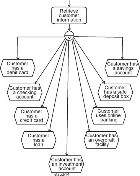
The following EPC fragment shows an example. In a customer inquiry, it is determined which services a customer uses. Since the person is already a customer, at least one result exists. The inquiry may therefore lead to any number of results. This situation can be modeled using a function followed by an OR operator and corresponding result events, as shown in the following figure. |
|
|
|
Figure 4.3-3: Event Connections / Generated Events / OR |
|
Short explanation of some of the banking products
- Checking account: A checking account is used for everyday financial transactions, such as receiving salary payments, paying bills, and making transfers.
- Debit card: A debit card is directly linked to the checking account. Payments and cash withdrawals are deducted immediately from the account balance.
- Credit card: A credit card allows the customer to pay without immediate withdrawal from the bank account. Expenses are billed later, usually once a month.
- Savings account: A savings account is used to store and save money. It is typically not intended for daily transactions.
- Overdraft facility: An overdraft facility allows the customer to spend more money than is currently available in the checking account, up to a defined limit. Interest rates are usually high.
- Loan: A loan is a larger amount of money provided by the bank for a specific purpose and repaid over a longer period of time.
- Investment account: An investment account is used to hold and manage securities such as stocks or mutual funds.
- Safe deposit box: A safe deposit box is a secure storage space at a bank for valuables or important documents. |
|
For generated events connected by an OR operator, the question often arises whether the events connected by OR are independent of one another, that is, whether each event can truly occur independently of the others in any combination. This can also be illustrated using the example above: |
Independence? |
- Online banking requires either a checking account or a securities account.
- An EC card requires a checking account.
- A loan is only granted if the borrower has an account.
|
|
There may be many such dependencies. By using the OR operator, these dependencies are deliberately not resolved. If this internal structure were also to be modeled, the EPC would become more complex. |
|
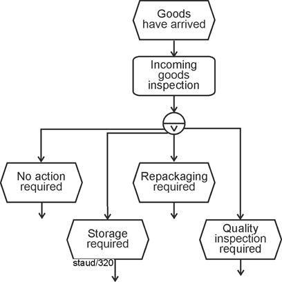
The domain-specific example shown in the following figure illustrates a similar situation. In this company, incoming goods inspection may lead to the goods being stored, repackaging being required, quality control being involved, or several of these activities occurring in any combination. So far, this corresponds to the "pure" logic of the OR operator. If one adds to these possible inspection results the event that signals that none of the other actions is required (No action required), the Event-Driven Process Chain shown in the following figure emerges. This is a natural and commonly used modeling approach. However, in this case the OR operator is no longer fully satisfied, because the event No action required cannot occur in combination with the others. The events are no longer independent of one another. |
|
This syntax therefore contradicts the OR operator, at least in its semantic interpretation, that is, when the meaning of the events is taken into account. Purely syntactically, if the only requirement is that at least one event must occur, the OR condition is still fulfilled. |
Syntax vs. Semantics |
|
|
Figure 4.3-4: Event Connections / Generated Events / OR
Incoming Goods Inspection |
|
The fact that events connected by OR should, in principle, be freely combinable, but that this is not always implemented (or possible) in practical modeling, can be described in terms of the independence or non-independence of events. |
Independence of Events |
A group of events connected by OR is independent of one another if the semantics allow the events to occur in any combination. |
Definition |
How such a structure - incorrect in the strict sense of the operator - can be transformed into a correct one is shown in [Staud 2025, Section 7.3]. |
|
4.4 Function Connections with Triggering Events |
|
Function connections with triggering events always mean that the occurrence of an event starts subsequent functions. This may be exactly one of several functions (XOR) (?), several functions together (AND), or at least one function (OR) (?). The question marks indicate that there are issues here that still need to be addressed. |
Event Triggeres Functions |
4.4.1 AND |
|
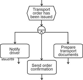
That an event directly triggers exactly one of several functions is generally considered undesirable in process modeling, because an event is not an activity in which a decision is made as to which function should be started. This will also be the topic of the next two sections (XOR, OR). With AND, however, there are no such problems. An event may lead to the parallel start of two or more functions. |
Well-Known: One Event Triggers Several Tasks |
The following example illustrates this. In a freight forwarding company, once a transport order has been issued, the driver must be notified, the order confirmation must be prepared, and the transport documents must be created. In this case, one can certainly assume that there is an order to these activities, but this order is deliberately not modeled when using the AND operator. |
No Order - or the Deliberate Omission of Order
Modeling |
|
|
Figure 4.4-1: AND / function connector / triggering event |
|
As always with the logical AND, the parallel arrangement does not mean that the tasks are actually carried out in parallel (certainly not in a technical sense), but only that they are started together. |
|
4.4.2 XOR - Not Permitted |
|
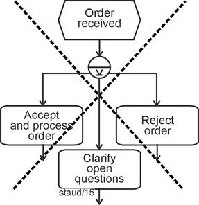
The following configuration is one that is not permitted by the originators of the EPC method. It concerns events that are followed by an XOR operator, thus triggering exactly one of several functions connected by exclusive OR. |
Missing Decision Function |
Let us consider the following example of an order being received. The event Order received is followed either by Accept order, Reject order, or Clarify open issues. If this situation is modeled as shown in the following figure, the EPC may appear appealing due to its simplicity. However, even brief reflection makes it clear that an important part of the real business process has not been modeled: decision-making, feasibility analysis, and similar activities. The EPC, so to speak, "jumps" directly from the event to the execution of one of the functions. |
|
|
XOR - not permitted |
Figure 4.4-2: Function connector / triggering event / XOR without decision function |
|
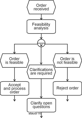
This is the reason why such a structure is, in a sense, prohibited. If it occurs, it must be extended by a function that models the decision process, and by events that express the possible outcomes of this decision process. The fragment shown above must then be modeled as in the following figure. |
|
|
Correct Solution with a Decision Function |
Figure 4.4-3: Function connections with preceding events / triggering event / XOR - with decision function |
|
With the introduction of the decision function (here: Feasibility check), the EPC also includes the events that indicate the possible outcomes of the decision process. These result events significantly increase the explanatory power of the EPC. |
|
4.4.3 OR - Not Permitted |
|
The following OR connector is again a prohibited one, exactly as in the case of the functions triggered by XOR described above. The example illustrates the situation when a new checking account is opened. Once this has been completed, the customer may request various services, ranging from an EC card to online banking. |
Missing decision function |
However, if the process is modeled as shown in the following figure, the decision function is missing - i.e., the function that determines which events actually occur in a concrete instance of the business process, and consequently which tasks are to be carried out. |
|
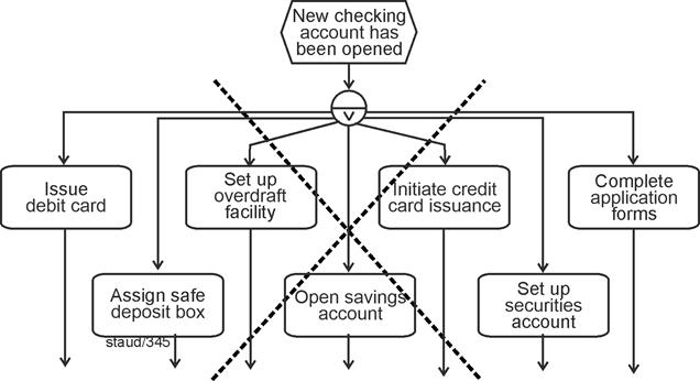
|
|
Figure 4.4-4: Function connector / triggering event / OR - without decision function |
|
Here, too, the decision-making process in the form of a function is missing. In the next figure, it is inserted together with the necessary events. The decision function can be described here as a decision made in consultation with the customer. A more detailed description of this problem, "Uncertainties in OR modeling," can be found in [Staud 2025, 7.3]. |
Correct solution with decision function |
A summary of all important syntax rules can be found in Chapter 6. Due to its great importance, the rule regarding prohibited structures is also listed here. |
|
Syntax rule |
|
After an event (or after several events), no OR or XOR operator may follow the functions that necessarily follow. In other words, triggering events with XOR and OR are not permitted. |
|
The following example shows the correct solution to the above situation. To ensure that they are not forgotten, organizational units and information objects have also been added here. |
|
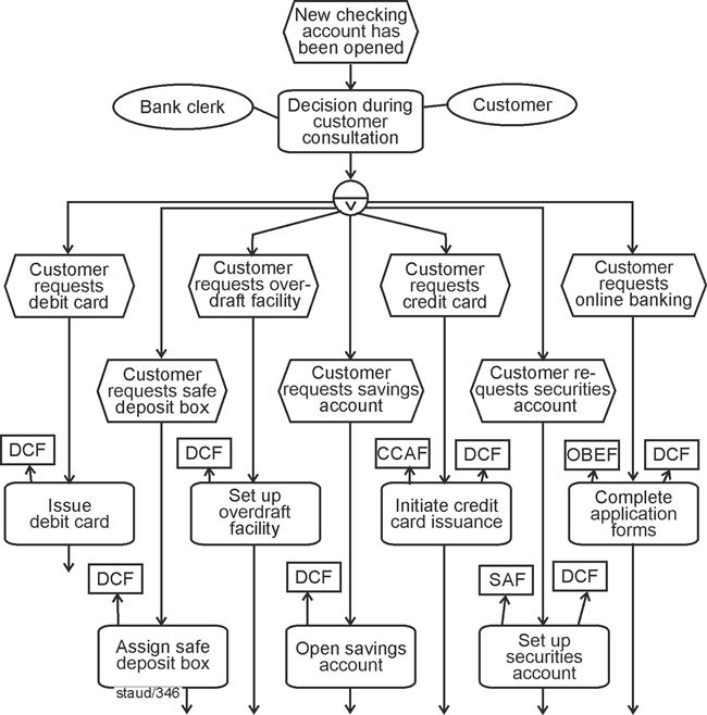
|
|
Figure 4.4-5: Function connector with preceding events / triggering event / OR - with decision function |
|
Remarks:
Semantics: An event triggers a subset of activities.
Syntax: Event, OR decision function with subsets of resulting events, followed by one function for each resulting event. |
|
|
|
Notes
DCF: Digital Customer File
CCAF: Credit Card Application Form
SAF: Securities Account Form
OBEF: Online Banking Enrollment Form |
|
4.5 Function connector with generated events |
|
Subsequent events generated by multiple functions occur when the completion of several functions can be represented by one and the same event. This always involves merging edges that originate from functions. In the case of XOR, these were alternatively executed functions; in the case of AND, functions to be completed in parallel; and in the case of OR, functions of which at least one had to be performed. |
Completion of functions |
4.5.1 AND |
|
Execute multiple functions, followed by a common resulting event. |
|
In this configuration, the logical AND means that several functions must be carried out before the subsequent event can occur. The functions must therefore be completed "simultaneously" before the business process can continue. Whether these activities are actually performed in parallel in reality is irrelevant from a modeling perspective. They may just as well be executed sequentially. |
|
In the following example, we assume that in a company, for every new hire, each applicant participates in an assessment center, an interview is conducted with the applicant, and the submitted documents are evaluated. Only after all of this has been completed does the selection process continue. |
|
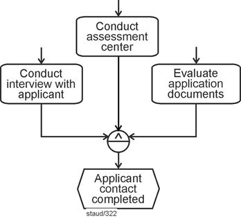
|
|
Abbildung 4.5-1: AND / function connector / generated event |
|
Remarks:
Semantics: Multiple activities have been completed; the business process continues in a unified manner.
Syntax: Multiple functions, connected by AND, followed by an event. |
|
Staffing a position - a more comprehensive example |
|
The model presented above is further extended in the following EPC in order to illustrate, by way of example, how such an EPC fragment can be embedded into a somewhat larger context. The business process starts with the desire to fill a position. This triggers a discussion of the approach to be taken, which is carried out jointly by the human resources department and the functional department and makes use of the staffing plan. |
|
A decision is made as to whether the position is to be advertised externally or filled internally. An internal placement proceeds smoothly (in this example). In the case of an external placement, an applicant file is created and a job posting is published, within which the three activities listed above are carried out: |
|
- Conduct interview with applicant
- Conduct assessment center
- Evaluate application documents
|
|
The results are recorded in the applicant file. Subsequently, based on the data obtained, a person is selected by the functional department and hired. |
|
The following EPC shows the implementation of this process description as a model. In addition to embedding the fragment shown above, the example also illustrates a pattern referred to here as a time window (see [Staud 2025, Section 6.3] for a more detailed discussion): the three activities are started after the first AND operator and completed before the second AND operator; only then does the process continue. |
Time window pattern |
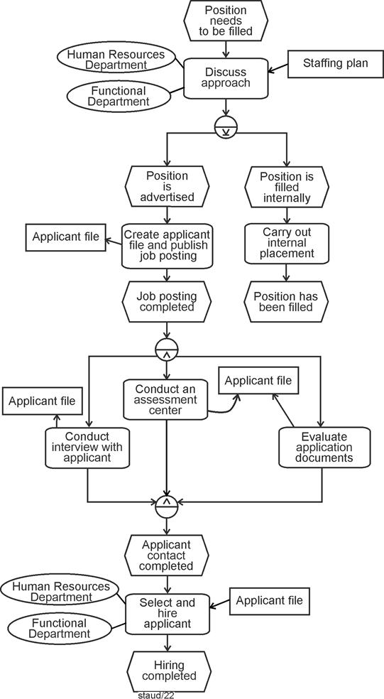
|
|
Figure 4.5-2: Staffing a position - possible embedding of the EPC fragment from Figure 4.5-1 |
|
Remarks:
Pattern: Time window
Syntax rule: Merging control flows |
|
This example also implements a syntax rule concerning the merging of control-flow branches (see [Staud 2025, Section 7.2]): if control flows are split by an operator and are to be merged again further downstream, the same operator that was used for the split must be used for the merge as well. |
Syntax rule: Merging control-flow branches |
4.5.2 XOR |
|
In the case of XODER, only one of the linked functions must and may occur here, then the jointly triggered event occurs. These are therefore alternatives with regard to the task to be performed, but they all lead to the same result. This is a structure that occurs very often in reality. |
Alternative activities with a single resulting
event: XOR |
Of course, instead of a single event, multiple events could also follow. In the following example, a shipment is carried out. It is performed either by one logistics provider or by another. Regardless of which one is chosen, the event Shipment completed occurs afterward. |
|
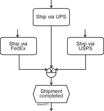
|
|
Figure 4.5-3: Function connector / generated event / XOR |
|
Three US shipping companies:
- UPS: United Parcel Service, Inc.
- FedEx: Federal Express Corporation
- USPS: United States Postal Service |
|
4.5.3 OR |
|
Triggered (i.e., subsequent) events following an OR connector mean that at least one of the functions must be carried out in order for the event to occur. In the following example, the event Available data compiled occurs if the preceding functions have been executed in the sense of OR ("at least one"). After that, calculation and quotation can be prepared. |
At least one function must be performed |
To make this EPC fragment easier to understand, the events and functions that precede the functions shown were also included in the figure. This also makes clear how such an arrangement can arise. |
|
The EPC fragment illustrates the final phase of a cost calculation in an industrial company. Depending on whether an identical system, a similar system, or individual components have been delivered before, different information bases are available. |
Semantics |
At least one of these conditions must be met in order to compile the available data. The OR connector ensures that one or more of the depicted functions are executed before the business process continues with the preparation of the cost calculation and quotation. |
|
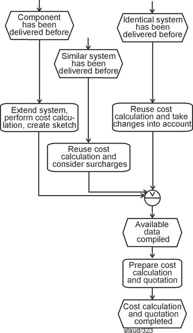
|
|
Figure 4.5-4: Function connector / generated event / OR |
|
4.6 Semantic meaning |
|
The meanings of the individual connectors are summarized in the following figure. For all twelve variants, the respective role of the events is indicated. This table therefore provides an overview of the possible combinations of events, functions, and connectors in the EPC control flow. It is structured along two dimensions. |
|
- The rows distinguish whether events or functions are being connected and whether the connector relates to triggering elements or generated elements.
- The columns show the semantics of the three logical connectors AND, XOR, and OR.
|
|
For each combination, the table specifies under which conditions events occur or functions are triggered, and how the completion of functions leads to subsequent events. Structures marked as PROHIBITED STRUCTURE violate EPC syntax rules and must not be used in valid models. |
|
Overall, the table serves as a compact reference for understanding the semantic meaning and syntactic constraints of connectors in EPCs. |
|
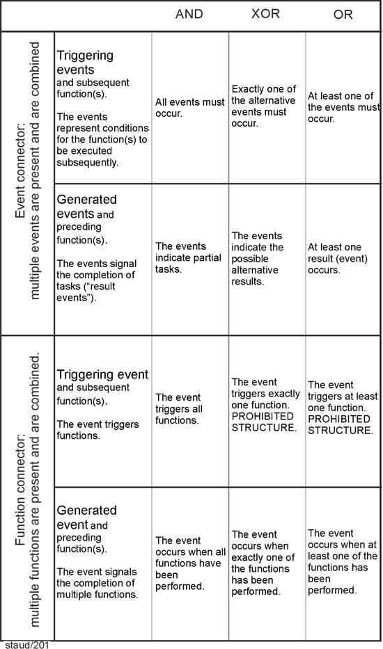
|
|
Figure 4.6-1: The role of events in the twelve connector variants |
|
5 EPC - An Commented Example |
|
The following example illustrates the basic elements and structure of Event-Driven Process Chains (EPCs). Each component is explained in its context so that readers can understand both the syntax and the underlying process logic. |
|
|
|
5.1 Inquiry examination, Part 1 |
|
The elements of Event-Driven Process Chains introduced above are connected in process modeling in order to obtain meaningful descriptions of business processes. Most of the rules applicable for this purpose are presented in this section. See also the collection of rules in Chapter 6. |
Rules for Creating Event-Driven Process Chains |
To enhance clarity, the explanation is based on a simple segment of a business process. This segment is described step by step (indented), followed by an explanation of how it is translated into the EPC. The resulting EPC is extended incrementally at each stage, in order to make the overall logic clear. |
|
What follows is a step-by-step description of a process. The associated texts are consistently indented. |
|
Process Segment: Inquiry Examination - Part 1 |
|
The following business process segment forms the basis of this example: In a manufacturing company producing custom-made products, it must be determined whether a customer's inquiry regarding a particular product can be fulfilled. |
|
The inquiry may arrive by email, by letter, or be formulated during a meeting. For letter-based inquiries, a response letter is prepared and sent. For email inquiries, the receipt of the email is confirmed, and for inquiries formulated during a meeting, an Order Specification (OS) is prepared and sent to the prospective customer. All of these activities are carried out by the Central Secretariat. |
|
Functions (work carried out) |
|
We begin with the core of every business process: the work carried out within it. In this example, three primary functions can be clearly identified: |
|
- Compose and send reply letter
- Confirm receipt of e-mail
- Create order specification (OS) and send it to the potential customer
|
|
The following figure shows the graphical representation of these functions. It also includes three additional functions that arise during the modeling process. |
|
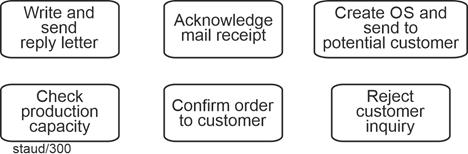
|
|
Figure 5.1-1: Graphical representation of functions |
|
OS: Order specification |
|
Events |
|
The start events are clearly identifiable from the process description: |
|
- Inquiry received by letter
- Inquiry received by e-mail
- Inquiry formulated during meeting
|
|
Since functions and events must always alternate in the control flow, each of the three functions is followed by an event that expresses its completion: |
|
- Reply letter sent
- Confirmation e-mail sent
- OS sent
|
|
In this configuration (clearly expressing completion), they may also be referred to as result events. All six of these events are shown in the following figure. |
|
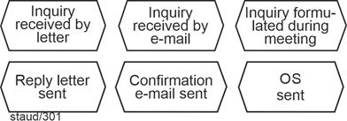
|
|
Figure 5.1-2: Graphical representation of events |
|
OS: Order specification |
|
Control Flow: Functions and Events Strictly Alternate |
|
Let us now turn to the control flow of this initial sequence. As a fundamental syntactic rule, functions and events must always alternate, and every business process must begin and end with an event. (The exception involving process navigators is discussed in Section 7.4.) The three start events mark the beginning of separate control-flow branches, each consisting of individual edges, as illustrated in the following figure. Each branch triggers a function, which is then followed by the result events mentioned earlier. The flow itself is expressed by the arrowed edges. |
|
Each function is associated with the organizational unit Central Secretariat, indicated by a non-directional line. |
|
Information Objects and Organizational Units |
|
The information objects were created in accordance with the process description: the incoming inquiry (whether a letter or an email) is connected to the function with an incoming arrow, and the resulting information objects, Order Specification, response letter, and confirmation email, are connected with outgoing arrows. The acting organizational unit in all of these cases is the Central Secretariat. |
|
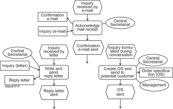
|
|
Figure 5.1-3: Business process Inquiry examination - start events and initial functions |
|
OS: Order specification |
|
5.2 Inquiry examination, Part 2 |
|
Process Segment: Inquiry Examination - Part 2 |
|
Next, the inquiry is entered into the ERP system by the Sales department. |
|
This is followed by two checks: one for the available production capacity (performed by the Production department), and one for the current inventory level (performed by the Warehouse department). In both cases, data from production planning or from the warehouse database is used. Each of these checks may yield either a positive or a negative result. |
|
The textual process description makes it clear that, regardless of which start event initiates the process, the control flow continues in a single branch. To merge the control-flow branches at this pint, the XOR operator must be used, because the start events are alternatives. As a general rule within an EPC, control-flow branches must be merged using the same operator that was used to split them (see [Staud 2025, Section 7.2]). This results in the following EPC fragment: |
Merging Control-Flow Branches
XOR |
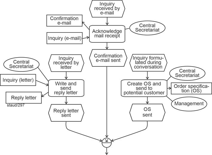
|
|
Figure 5.2-1: Business process "Inquiry examination" - Merging Alternative Start Sequences (XOR merge) |
|
The next step is the creation of the inquiry in the ERP system, which results in a new information object: InquiryERP. For this reason, the arrow points to the information object. This example illustrates how information objects are handled in Event-Driven Process Chains. First, the Inquiry (letter/email/OS) [Anmerkung] is read, and then InquiryERP is written. This sequence is not expressed explicitly in the model; it must be inferred from the process description or from the process context. |
1. Reading
2. Writing |
The next part of the business process becomes more interesting. The process description specifies a pattern that is frequently encountered in business processes: multiple functions (activities) are triggered simultaneously. As discussed in [Staud 2026, Section 6.2], this can be implemented using an AND operator, as shown in the following figure. The AND operator requires that both functions - Check production capacity and Check inventory - be initiated. |
Pattern: Triggering Multiple Activities |
The organizational units mentioned in the process description are attached accordingly. The information object InquiryERP serves as input for both functions, as do the requested data sets (production planning and the inventory database). |
|
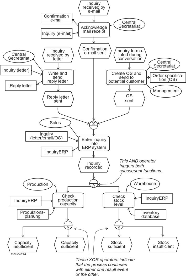
|
|
Figure 5.2-2: Business process request review - triggering two functions using the AND operator and the decision-making pattern |
|
Of course, each of the two new functions leads to results, which are modeled as events [Anmerkung] . According to the process description, each function can yield either a positive or a negative outcome: |
|
- Capacity sufficient and capacity insufficient for the Check production capacity function
- Inventory sufficient and inventory insufficient for the Check inventory function
|
|
Since these outcomes are mutually exclusive, an XOR operator must be inserted into the control flow at each of these points. |
|
5.3 Inquiry examination, Part 3 |
|
Process Segment: Inquiry Examination - Part 3 |
|
In the positive case - meaning that both the production capacity is sufficient and the inventory level is adequate - a confirmation is sent to the customer by the Sales department. The information object InquiryERP is required for this step, and the confirmation is also recorded there. In addition, the necessary customer information is read from the customer database, and the fact that the inquiry was answered positively is stored there as well. |
|
After this, the business process Order Processing is initiated. |
|
This semantics is implemented in an EPC by merging the control-flow paths of the two positive events, connecting them with an AND operator, and directing the combined flow to the corresponding function - in this case, Accept customer request. A brief reflection shows that this EPC syntax indeed captures the semantics required by the process description: the flow continues only if both control-flow paths arrive at the AND operator from their respective events. |
Semantics Seeking Syntax |
For the function Accept customer request, the designated organizational unit and both information objects are attached. Each of them is read and written, which is why the arrows on the connecting lines point in both directions. |
|
Semantics Seeking Syntax |
|
In every domain-specific modeling context, there are not only straightforward structures to be represented, but also more complex semantic aspects that should be reflected in the model. The same holds in process modeling. In such cases, the task is to find the appropriate syntactic construct of the semi-formal modeling language to represent the intended semantic meaning. |
|
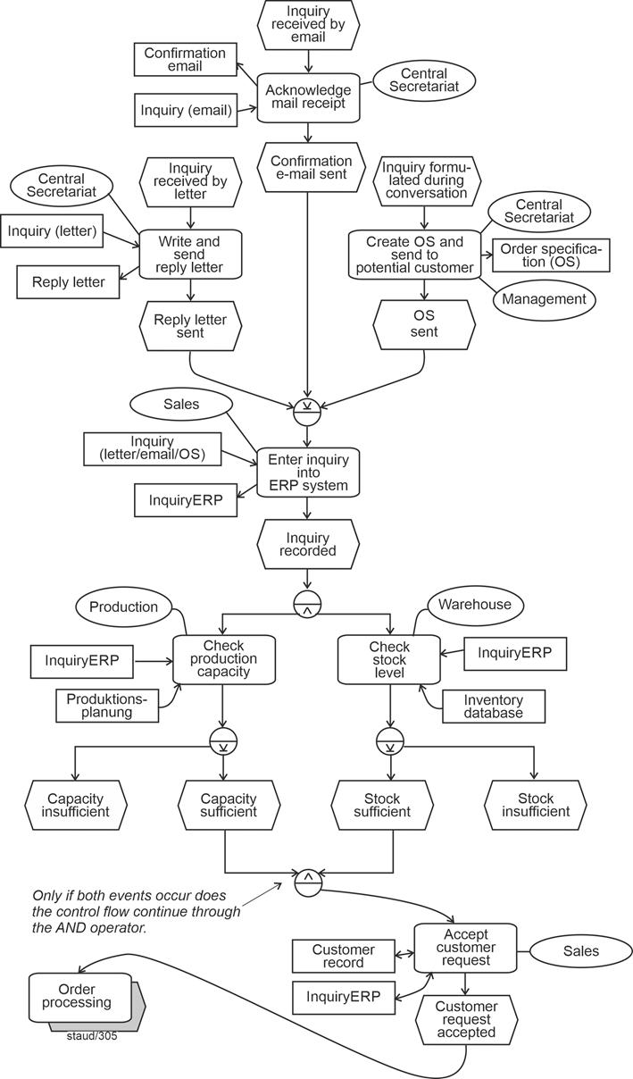
|
|
Figure 5.3-1: Business process request review - positive outcome and invocation of order processing |
|
Bidirectional Arrows: Reading and Writing |
|
Reference to another EPC using a Process Navigator |
|
Since the process description specifies the positive end result at this point, namely the invocation of the subsequent business process Order Processing, a process navigator can be used to reference the corresponding EPC. Let us take this as the first example of a process navigator, that is, a reference to another process. Process navigators are introduced in detail in [Staud 2025, Section 7.4]. |
|
The figure above shows the state reached within the business process Inquiry Examination, and the following figure shows the beginning of the business process Order Processing. |
|
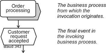
|
|
Abbildung 5.3-2: Start of the business process "Order Processing" |
|
The AND operator, which has already appeared several times, indicates that the control flow proceeds only if all incoming control-flow paths from upstream arrive at the operator. In this configuration - events connected by an AND operator immediately before a function - the events always represent conditions for the execution of the subsequent function. |
The Conditions Pattern |
5.4 Inquiry examination, Part 4 |
|
The process description now turns to the negative outcomes. |
|
Process Segment: Inquiry Examination - Part 4 |
|
If either the production capacity or the inventory level is insufficient, the Sales department sends a rejection to the customer. For this step, the information object InquiryERP is required, and the rejection is recorded in it. In addition, the customer database is updated to document that the inquiry could not be fulfilled. |
|
The process description makes the situation clear: if either of the two checks yields a negative result, the customer is to be rejected. This situation corresponds to what is referred to here as the pattern of combinatorics. The reason is that the result events of the two functions must be combined in order to capture all possible continuations of the business process: |
The Pattern of Combinatorics |
|
1. Capacity insufficient - inventory sufficient
|
|
|
2. Capacity insufficient - inventory insufficient
|
|
|
3. Capacity sufficient - inventory sufficient
|
|
|
4. Capacity sufficient - inventory insufficient
|
|
Semantics Seeking Syntax: Combinatorics Implemented Using the AND Operator |
|
The following figure illustrates this general approach. For all four constellations, the process continues and leads to a corresponding function. The AND operator is extremely useful here - again in the sense of finding a syntax that captures the intended semantics. Since the control flow proceeds through the AND operator only when all outgoing or incoming edges are activated (only the edges, not the subsequent functions!), this syntactic solution produces exactly the desired semantics. |
|
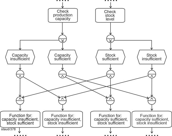
|
|
Figure 5.4-1: Combinatorics Fully Realized |
|
In this specific business process, the positive variant (the positive case) has already been handled above. What remains are the three cases in which either one check or the other, or both, yield a negative result. These can be consolidated here, since a negative outcome in either check always leads to termination of the process. |
From Three to One |
Matching Semantics to Syntax: "At Least One Event" Using the OR Operator |
|
The implementation of this semantics in the syntax of an Event-Driven Process Chain (EPC) is shown in the following figure. An OR operator is placed before the function Decline customer request, merging the control-flow branches of the two negative result events. An OR operator must be used here because either one event, or the other, or both should cause the control flow to proceed through it to the function Decline customer request and then to the subsequent event Customer declined. With this, the business process ends in two possible final events. The following figure shows the final result. |
|
In practice, this occurs quite frequently: a large number of combinations (imagine, for example, 5 outcome events on one side and 4 on the other) is often reduced through an appropriate semantic interpretation. |
|
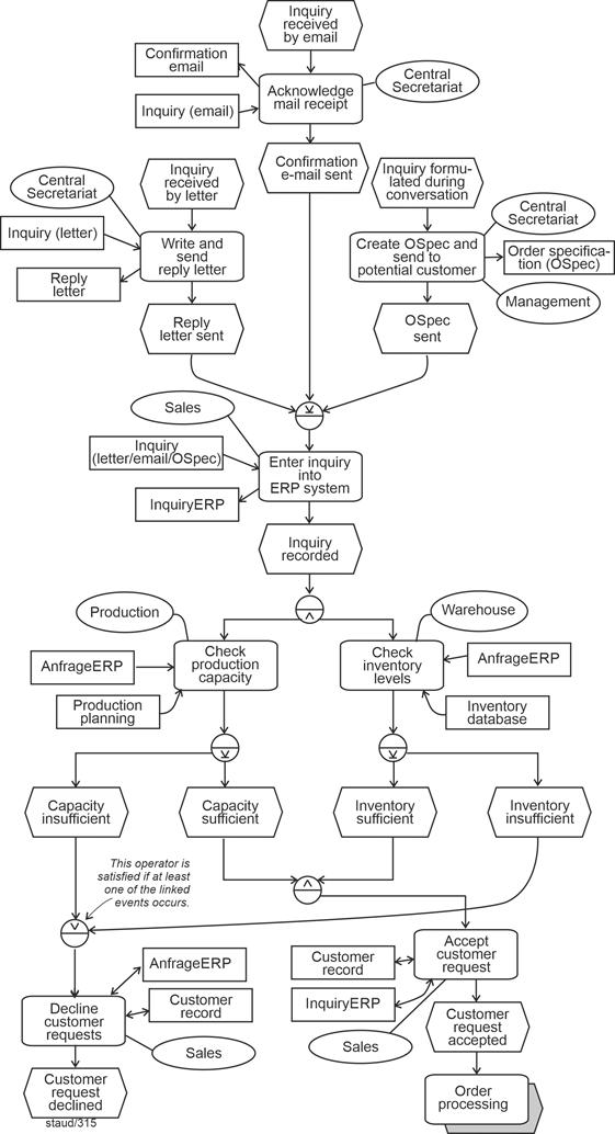
|
|
Figure 5.4-2: Business process request review - the final EPC |
|
5.5 Instances |
|
The event-driven process chain (EPC) created above shows all possible paths through the process - the complete control flow. However, it is sometimes useful to consider a single, specific execution with its specific control-flow path. Such an EPC is referred to as an instance of the "general" EPC, and the corresponding individual process execution is an instance of the "general" business process. |
Control Flow: Individual Runs |
The following figure shows an instance of the EPC that represents the positive case (the order can be accepted and the subsequent process can be started). The control flow is highlighted by a bold and dashed line. The start event is Inquiry received by e-mail, though either of the other start events could also apply. The subsequent flow is identical for all instances up to the AND operator and the two functions that follow it. That is, the AND operator always triggers all of its outgoing control-flow branches. |
Control Flow for the Positive Case |
From this point onward, differences between instances appear. In this positive case, both checks yield positive results. The corresponding flow paths are therefore highlighted. From the two positive result events (Capacity sufficient, Inventory sufficient), the active paths continue to the AND operator and - since both arrive - to the function Confirm to customer. The process connector then leads to the subsequent business process. |
|
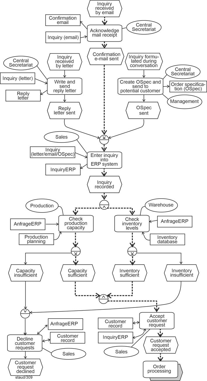
|
|
Figure 5.5-1: Business process inquiry examination - instance for the positive outcome |
|
Control Flow for One of the Negative Cases |
|
The next figure shows another instance, one that leads to a negative outcome. Again, the active control-flow edges are highlighted. |
|
Here, the start event is Inquiry formulated during conversation. The corresponding function follows, and then, after the XOR operator, the inquiry is entered into the ERP system. The control flow up to the two checks triggered by the AND operator is identical to the positive case. However, one of the checks (Production capacity check) produces a negative result. As a consequence, the control flow proceeds immediately to the function Reject to customer. |
|
The check for inventory level yields a positive result in this instance and reaches the following AND operator. However, the control flow cannot continue through the AND operator, because an AND operator only allows control flow to proceed when all incoming branches are active. The inactive branch is therefore effectively blocked - this point is marked with an exclamation symbol in the diagram. Thus, once again, the semantics are accurately expressed through the EPC syntax. |
Matching Semantics to Syntax |
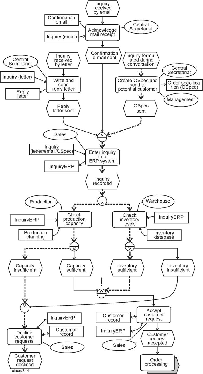
|
|
Figure 5.5-2: Business process inquiry examination - Instance for a negative outcome |
|
|
|
6 The Rule Set for Creating EPCs |
|
One of the major advantages of Event-Driven Process Chains is that their construction can be described using only a small number of rules. This is due to their clear structure and the fact that, unlike other process modeling methods, they do not exhibit numerous variants or unresolved areas. The most important rules relating to syntax, pragmatics, and graphical layout are presented below. |
|
|
|
6.1 Syntax Rules |
|
Rules for the syntactically correct construction of EPCs |
|
Not only formal languages, but also semi-formal languages are governed by rules that define the permissible connections between elements. These rules have been described in detail for Event-Driven Process Chains in the preceding text and are summarized below: |
|
- (Start) At the beginning of each control flow branch there is one event (or several events). If this event is also located at the beginning of the EPC, it is referred to as a start event.
- (Start) In the case of invoked processes, the process interface precedes the start event and is labeled with the name of the invoking process.
- (End) At the end of each control flow branch there is one event (or several events). These are referred to as end event(s).
- (Control flow) Events are connected only within the control flow and only to functions.
- (E-F sequence) Except for start and end events, the following applies to the control flow: an event is followed by a function, and a function is followed by an event. Events and functions therefore alternate.
- (OU) Organizational units are assigned to functions in which they participate (more precisely, in which employees of the respective organizational unit are involved). The assignment is represented by an undirected line.
- (IO 1) Information objects are assigned to functions for which they are required. The assignment is represented by a directed arrow.
- (IO 2) If an information object is created or modified as a result of the activities of a function, the arrow points toward the information object.
- (IO 3) If an information object is used within a function, the arrow points toward the function.
- (IO 4) Merely perceiving or viewing an information object is not expressed by an arrow. Otherwise, every access to an information object would require modeling a read operation (arrowhead pointing to the function).
- (IO 5) If an information object is only transported within the scope of a function, no arrowhead is shown.
- (Operators 1) Branching and merging of control flow branches may only be performed using operators.
- (Operators 2) Operators always connect either multiple events or multiple functions.
- (Operators 3) OR operator (syntactic). If events are connected: at least one of the connected events must occur before the control flow continues.
- (Operators 4) OR operator (syntactic). If functions are connected: at least one of the connected functions must be performed before the control flow continues.
- (Operators 5) XOR operator (syntactic). If events are connected: exactly one of the connected events must occur before the control flow continues.
- (Operators 6) XOR operator (syntactic). If functions are connected: exactly one of the connected functions must be performed before the control flow continues.
- (Operators 7) AND operator (syntactic). If events are connected: all connected events must occur before the control flow continues.
- (Operators 8) AND operator (syntactic). If functions are connected: all connected functions must be performed before the control flow continues.
- (Control flow 1) Triggering events combined with XOR or OR are not allowed. That is, after an event (or multiple events), no OR or XOR operator may follow for the necessarily subsequent functions.
- (Control flow 2 - backward jumps) Backward jumps remain within the same control flow branch. They originate from an event upstream and are reintroduced into the control flow before a function.
- (Control flow 3 - merging edges) Edges are merged using the same operator by which they were split upstream.
- (Control flow 4 - merging edges) When merging control flow branches, it must be ensured that the correct event-function sequence is established before the merging operator.
- (Control flow 5 - nested flows) If multiple nested branches have been opened and are to be closed, the innermost branch is closed first, followed by the next, and finally the outermost branch (exactly as in the control structures of procedural programming).
- (Control flow 6) If the control flow continues uniformly after an OR or XOR branch (within a single control flow branch), all branches must be merged before attaching further functions and events.
- (Process interface 1) In the invoking process, the process interface appears in place of a function. It is labeled with the name of the invoked process.
- (Process interface 2) In the invoked Event-Driven Process Chain, the process interface is located at the beginning of a control flow branch. Its label indicates from which other EPC the invocation originates. It is followed by the event that precedes the process interface in the invoking process. Instead of one event, there may also be several events.
- (Time aspects 1) The temporal dimension of a business process is expressed by the sequence of events and functions.
- (Time aspects 2) A specific point in time is modeled by creating a corresponding temporal event and integrating it into the control flow using an AND operator.
|
|
6.2 Recommendations on Pragmatics |
|
References to the role of pragmatics in the design of Event-Driven Process Chains are provided at many points throughout the text. Some particularly important examples are described in Section 7.8 of [Staud 2025]. The most important related rules are summarized below. |
|
- (Abstraction) When connecting functions using OR or XOR, the individual result events of the functions may be omitted. Instead, an abstracted (common) result event (for example, "completed") can be used. The control flow branches must be merged before this event.
- (Backward jumps) No control of the number of backward jumps [Staud 2025, Figure 6.8-1].
- (Repetition) No backward jump for repetition [Staud 2025, Figure 6.8-2].
- (Relationships within a time window) No consideration of the relationships between the functions within a time window [Staud 2025, Figure 6.3-1], or following an AND operator [Staud 2025, Figure 5.4-2].
- (Decisions) "Merging" of two operators or decisions (see [Staud 2025, Section 7.3].
- (Combinatorics) Simplification by abstraction in cases of branching caused by combinatorial explosion (see [Staud 2025, Section 7.3]).
|
|
It becomes clear that pragmatics in this context usually means refraining from excessive (and unnecessary) precision. This is generally the case in modeling, and in process modeling in particular. Ultimately, we are modeling only standard procedures (routine processes). More is not possible, because the complexity of real life always exceeds that of any model. |
|
Note from January 2026: In light of current developments in artificial intelligence, the remark above may already (or soon) be outdated. AI agents (or similar software products) could help manage the complex diversity of business processes. However, several fundamental shortcomings of current AI solutions would still need to be addressed, such as "hallucination," the energy consumption required for model creation, susceptibility to manipulation through the data basis, and similar issues. |
|
6.3 Design Rules |
|
Additional rules that contribute to the final form of Event-Driven Process Chains are the design rules presented in [Staud 2025, Section 1.2] and here in Section 3.10. The most important ones are listed below: |
|
- (Organizational units) Omit organizational units if they are the same as for the preceding function.
|
|
If two consecutive functions are both performed by the Sales department, the organizational unit needs to be shown only once. It is omitted for the second function to keep the diagram concise. |
|
- (Information transport) Represent information transport without indicating an arrow direction.
|
|
If a document is merely passed from one function to the next without being modified, the information object is connected without an arrowhead, indicating pure transport. |
|
- (Omitting events) Omit events in an unbranched sequence.
|
|
In a simple, linear sequence of functions without any branching, intermediate events may be omitted. The process flow is still clear and easier to read. |
|
|
|
This concludes the discussion of Event-Driven Process Chains. A more detailed presentation can be found in [Staud 2025] and - of course - in the books by Scheer et al., the originators of the method. In the author's view, Event-Driven Process Chains are particularly well suited as an introduction to the topic of business processes and process modeling. They support the understanding of process-oriented thinking and enable the acquisition of initial methodological competence. EPKs are also, for example, the method of choice for as-is analyses. |
|
The following chapters present the fundamentals of the Business Process Model and Notation (BPMN) method. In this concise overview, the focus is placed on the most important theoretical elements. Even this brief treatment should make clear that Business Process Diagrams (BPDs - this is what BPMN process models are called) are significantly more complex than EPKs and allow for a more detailed modeling of business processes. As a result, they are particularly well suited for modeling in the context of software engineering, that is, for preparing an implementation in software.
For further study, a publication by the author is also available [Staud 2024], as well as the texts by the originators of the method, including [OMG 2003], [OMG 2009], [OMG 2011], and [OMG 2013]. |
|
|
|
|
|
7 Business processes in the BPMN |
|
Preliminary note: For all references to [Staud 2024], the following applies: A short version of this book is available on my website at https://www.staud.info/bpmn2/bp_t_1.php |
|
Let us begin with two quotations from the originators of the method. The first concerns its purpose: |
|
"Business Process Model and Notation has become the de-facto standard for business processes diagrams. It is intended to be used directly by the stakeholders who design, manage and realize business processes, but at the same time be precise enough to allow BPMN diagrams to be translated into software process components. BPMN has an easy-to-use flowchart-like notation that is independent of any particular implementation environment". [https://www.omg.org/spec/BPMN/2.0.2/About-BPMN/, retrieved November 11, 2025] |
|
The second relates to the realization of process modeling: |
|
"BPMN depicts the end to end flow of a business process. The notation has been specifically designed to coordinate the sequence of processes and the messages that flow between different process participants in a related set of activities." [http://www.bpmn.org/, retrieved July 2, 2016] |
|
Using BPMN, business processes can be systematically analyzed and simulated. It provides the foundation for a process engine, i.e., software that controls processes. Symbols are used to draw process diagrams. In its current version, BPMN 2.0.2, the method comprises more than 100 elements. |
|
|
|
7.1 Definition |
|
How do the BPMN authors define business processes? In the original text, the following explanations can be found: |
|
- A business process describes a goal-oriented sequence of activities within an organization. It consists of multiple activities and the sequence flow mechanisms that structure them [OMG 2011, p. 145].
- There are three types of processes: Private Non-Executable (internal) Business Processes, Private Executable (internal) Business Processes, and Public Processes [ibid., p. 149].
- Processes exist at multiple hierarchical levels. They can be defined across the entire organization or along the activities of a single individual [ibid., p. 32].
- Processes at a lower level of aggregation (low-level processes) that together perform a task can be grouped.
- Each process may have its own subprocesses and can be contained within a pool.
- Individual processes can be independent from one another in terms of sequence flow, yet connected through one or more message flows.
- There is a central unit controlling the business process (central controller, responsible entity, or observer) [ibid., p. 25].
|
|
The BPMN authors emphasize the following distinction in this context: the term process is used for "a set of flow elements", while the interaction between processes is described by the terms collaboration and choreography. |
|
7.2 Process Types in BPMN |
|
Private Business Process |
|
The term Private Business Processes refers to those realized within a single company (or organization). In this text, they are referred to as internal business processes. Two types are distinguished: executable and non-executable. |
|
An executable process (Private Executable (internal) Business Process) is one that is designed to be represented in WS-BPEL. Its compatibility with the Business Process Execution Language makes it executable. |
|
A non-executable process (Private Non-executable (internal) Business Process) is one that is realized within an organization but not intended for software execution. The modeling of such processes serves other purposes - for example, documentation, as-is analysis, or obtaining an overview (at a higher level of aggregation). |
|
Because the assignment of actors to individual activities in BPMN is represented using the swimlane technique with pools and lanes (see [Staud 2024, Section 7.1]), the BPMN authors can also state that internal processes occur within a single pool. The sequence flow cannot leave the pool. Interactions across pool boundaries are modeled in BPMN through message flows, which represent the necessary communication between different organizations (see [Staud 2024, Section 7.2]). |
|
Public Processes |
|
The term Public Process refers to processes that take place between an internal business process and another process. In this text, they are referred to as public business processes. |
|
A public process thus includes the activities that serve communication with partners and the arrangement of those activities [OMG 2011, p. 150]. All other internal activities of the respective (other) internal process are not shown in public processes. They are modeled independently or as part of a collaboration. |
|
Global Processes |
|
Business processes that can be invoked by the call activities of other processes are referred to by the BPMN authors as global processes. They belong to the category of subprocesses, are reusable, and can have multiple start events. |
|
7.3 Diagram Types |
|
The following types of diagrams can be modeled using BPMN: |
|
- Highly aggregated internal processes
- Detailed internal business processes (as-is processes, to-be processes)
- Detailed internal business processes with interactions involving one or more external partners
- Two or more detailed internal business processes that interact with each other
- Detailed business processes with relations to a public process
- Relations between a detailed internal business process and a global process
- Two or more public processes
- Relation(s) between a public process and a global process
- A single global process
- Two or more detailed internal business processes that interact through a public process
- Two or more detailed internal business processes that interact through a global process
- Two or more detailed internal business processes that interact through their abstract processes and a collaboration process
|
|
[OMG 2009, pp. 14 f.] In [OMG 2011], this classification is no longer presented in such detail, but rather summarized with the note that processes can be modeled at all conceivable levels [OMG 2011, p. 145]. |
|
Vertical Dimension of Process Modeling |
|
In the above list, the vertical dimension of process modeling implicitly introduces a natural distinction between |
|
- highly aggregated activities of internal processes, and
- detailed internal business processes.
|
|
In the explanations provided by the BPMN authors, the top-level business processes - that is, the processes at the highest level of abstraction - play a special role within their respective modeling context. For these processes, specific methodological conventions apply. |
|
7.4 Grouping of Elements |
|
The BPMN authors divide the method elements used into four categories: |
|
- Flow objects
- Connecting objects
- Swimlanes
- Artifacts
|
|
Flow objects are further subdivided into: |
|
- Events
- Activities
- Gateways
|
|
Connecting objects are those used to link flow objects with one another: |
|
- Sequence flow
- Message flow
- Associations
|
|
Swimlanes serve to group the basic modeling elements. A distinction is made between: |
|
|
|
|
Artifacts provide additional information about the process. Three are predefined, while others may - according to the BPMN authors - be added as needed: |
|
- Data objects
- Groups
- Annotations
|
|
7.5 Tokens |
|
Just as the UML authors do, the BPMN authors also use the token concept to describe process behavior. As discussed in [Staud 2019], it serves to illustrate the control flow - in this case, the sequence flow. A token essentially moves along the sequence flows, passing through the other process elements (e.g., operators/gateways). The role of each process element within the process can thus be explained through the behavior of tokens as they interact with these elements - a perspective that will be revisited repeatedly throughout this text. Tokens are generated at start events and consumed at end events. |
|
Nodes and Edges |
|
In connection with tokens, the terms nodes and edges are used. These two concepts originate from graph theory (=>graph). |
|
- In BPMN, a node represents an activity or a subprocess,
- while an edge represents a connection between two nodes, such as a sequence flow or a message flow.
|
|
Whereas edges in graph theory may be directed or undirected, they are always directed in process modeling. |
|
Nodes and edges follow rules for token flow. For example, |
|
- nodes define when tokens may (so to speak) enter or leave them,
- edges define when a token may be accepted from the source node and transferred to the target node.
|
|
A token traverses an edge only when all rules for the target node, the edge, and the source node are satisfied. |
|
Control nodes (i.e., gateways or operators) serve as path controllers for the tokens. According to their semantics, they direct the tokens - and in the case of AND operators, may even duplicate them. |
|
Thus, a token moves through the execution sequence and the flow objects of the process. The process behavior can be described by tracing the individual token paths through the process. When observing the token flow of a specific execution, a business process instance is created. |
|
Tokens and Instances |
|
A process instance is initiated by the arrival of a token. For the instance to be completed, all tokens within it must reach an end node - that is, a node without outgoing sequence flows. |
|
When a token reaches an end event, it triggers the behavior associated with that event type - for example: |
|
- a linked message in a Message End Event, or
- a linked signal in a Signal End Event.
|
|
If the token reaches a Terminate End Event, the entire process is terminated. A process instance is considered complete when the following three conditions are met: |
|
- If the instance was created by an instantiating parallel gateway, all subsequent events of that gateway must have occurred.
- No tokens remain within the process instance.
- No activity within the process is still active.
|
|
Further specifications concerning token flow can be found in the descriptions of the respective method components. |
|
|
|
8 BPMN - Introductory examples |
|
|
|
8.1 The First Business Process Diagram |
|
At first glance, it looks quite familiar - especially to those who are already acquainted with UML methods (particularly activity diagrams) and Event-Driven Process Chains. There is a graphical element that represents activities: a rectangle with rounded corners. It is used to describe what is actually done within the business process, that is, into which individual elementary activities the process has been decomposed. This element is called an activity. For more details, see [Staud 2024, Chapter 6]. |
|

|
|
Figure 8.1-1: Representation of an activity (subprocess, task) |
|
The sequence flow specifies the order in which the individual activities are carried out in a business process. It is represented by directed arrows that connect the individual activities. In addition, the method defines start and end events - circles with thin and thick borders, respectively - to mark the beginning and end of a business process. With these elements, one can already construct a first, albeit very simple, Business Process Diagram (BPD), the term used here for process models, representing a sequence of activities that, once initiated, are carried out one after another. |
|
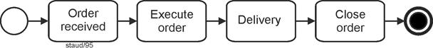
|
|
Figure 8.1-2: Order processing - Variant 1 |
|
Elements used, from left to right: Start event (Top Level), four activities, end event (Terminate). |
|
Of course, the actual process behavior is not as simple as shown above, and much of what one would normally expect in process modeling is still missing here - more on that later. In the example above, what is most noticeably absent is the decision on whether the order is accepted at all, as well as the branching of activities into parallel paths: order processing on the one hand and payment processing on the other. This is, of course, possible; the necessary operators (called gateways here) are available in the method. |
|
Let us now examine the following figure. In it, the above Business Process Diagram (BPD) has been slightly extended. It also contains numbered circles, which are not part of the BPMN method itself but serve only as references for the following explanations. |
|
As in the previous figure, there is a start event (1), which triggers the activity Receive order (2). This is followed by the first branching point, represented by an operator (3). Specifically, this means that one sequence flow splits into several. The process continues either along the branch Order rejected (4) or along the branch Order accepted (5). |
|
The operators are called gateways by the BPMN authors. The graphical symbol is a diamond shape (a square rotated forty-five percent). The figure below contains several of them. The first one (3) represents an operator of the exclusive OR type (XOR, see below as well as [Staud 2024, Section 11.2] for a detailed description). The BPMN authors refer to it as an Exclusive Gateway. It can be briefly described as follows: |
Gateways |
After the gateway, there are multiple outgoing paths, but only one of them can become active. |
|
The slash next to "Accepted" indicates the default path, which in this modeling approach simply means that it is the one most frequently taken. |
|
The path representing the rejection of the order leads directly to the end of the business process, merging at a gateway (8) that combines multiple paths - more on this shortly below. |
|
In the positive case ("Accepted"), the activity Execute order is performed. Once this is completed, two activities are triggered: |
|
- Delivery, and
- Send invoice.
|
|
For such a situation - essentially, the simultaneous triggering of two activities - an AND operator is used, referred to here as a Parallel Gateway. This gateway type exists in all process modeling methods and is represented by a plus sign (+). The AND gateway at position (6) is a diverging one; further downstream, another converging one follows (7). |
|
In many examples by the BPMN authors, such an operator symbol is omitted, and the sequence flows are shown diverging or converging without an explicit symbol. Based on the author's experience, such modeling leads to confusion and should therefore be avoided. More information on gateways can be found below and, in more detail, in [Staud 2024, Chapter 11]. |
|
The parallelism created by the gateway (6) here means that both outgoing paths are initiated and their activities are executed. "Parallel" in this context simply means simultaneous initiation, not actual parallel execution. Since there is only one outgoing sequence flow afterward, both paths must be merged again. For this purpose, the same type of gateway is used (7) - the Parallel Gateway - since both sequence flows originated from one. This reflects a general rule of process modeling: |
|
To merge sequence flows, the same operator type must be used that was applied when splitting them. |
|
At the end of the business process, on the right-hand side of the figure, the flows separated by an Exclusive Gateway are merged again (8). Once again, an Exclusive Gateway is used for this purpose. The BPMN authors refer to this as exclusive merging. In this case, it represents the data-based variant; there is also an event-based variant. Further details can be found in [Staud 2024, Chapter 11]. Finally, the process concludes with the end event (terminate) (9). |
|
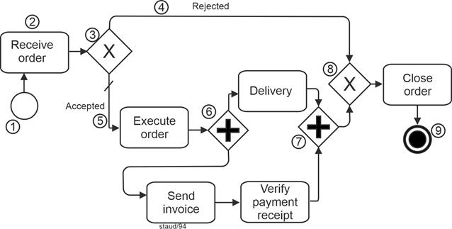
|
|
Figure 8.1-3:Order processing - Variant 2
Source: Adapted from [OMG 2009a, p. 104, Figure 10.12] and [OMG 2011, p. 269, Figure 10.85] |
|
Elements included:
- Start event
- Exclusive gateway with default setting
- Task
- Parallel gateway, diverging
- Parallel gateway, converging
- Exclusive gateway, converging
- End event |
|
So much for the first "presentable" business process as a BPD. However, it still lacks several important components - for example, the data objects it manipulates and the specification of responsibilities. |
|
8.2 Now with Data |
|
Data objects are all business objects such as invoices, delivery notes, and so on; any kind of coordination information (requests, offers, delivery notifications); and, of course, the organization's regular database with all its data records. They are of great importance for every business process, which is why every method for business process modeling must provide a way to represent them. |
|
Strictly speaking, the term information object would be more accurate, since business objects and their representations in process models also carry semantic meaning, which belongs more to the realm of information than of data. For simplicity, however, the term data objects is used here. |
|
In BPMN, data objects can be assigned to an activity or to a sequence flow. They can also be depicted in their own flow, parallel to the sequence flow. In the following figure, two data objects are included. First, the order, which enters the organization and thereby triggers the business process. It is simply assigned to the activity Receive order. The arrowhead indicates the information flow. The second data object in this example is the invoice, which is assigned to the activity Send invoice. |
|
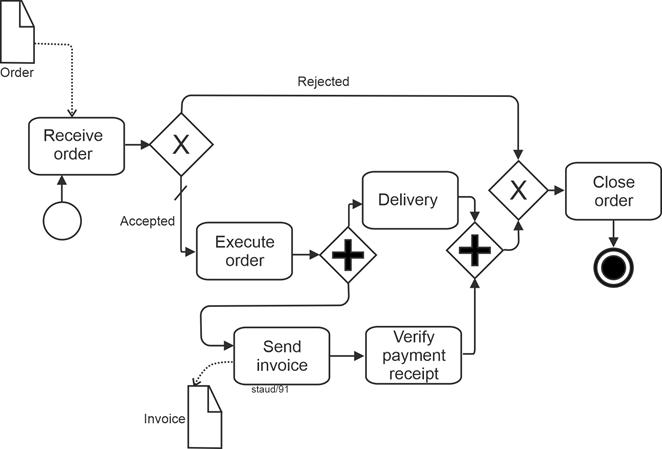
|
|
Figure 8.2-1: Order Processing - Variant 3
Source: Adapted from [OMG 2009a, p. 104, Figure 10.12] and [OMG 2011, p. 269, Figure 10.85] |
|
Elements included - in addition to the previous figure:
- Data object |
|
Further information on data objects can be found in [Staud 2024, Chapter 8]. |
|
8.3 Actors - Performers of Activities |
|
For a basic configuration of a process modeling method, the only remaining elements to be added are the actors involved in the business process - the performers of activities. These are first assigned to the individual activities. Possible performers include people or software systems, with or without machines [Anmerkung] . |
|
To assign activity performers to larger organizational units, the BPMN authors adopted the well-known swimlane technique. In this approach, pools and lanes are used: |
|
- Pools represent higher-level performers (e.g., entire companies),
- Lanes represent subordinate ones (e.g., departments or individuals in specific positions).
|
|
The following figure illustrates the extended introductory example. |
|
The upper pool contains all activities carried out by the company under consideration. It is further divided into two lanes: one for the Order Processing Department and one for the Finance Department. The activities are placed in the lane of the department responsible for performing them. The sequence flow then runs back and forth between the lanes as appropriate. |
|
From this point onward, we include the customer as well. This allows two complementary theoretical concepts to be demonstrated: first, that independent participants in the process each receive their own pool, and second, that information exchange across pool boundaries must, in BPMN, be modeled as a message flow. For this reason, the following figure includes a separate Customer pool. |
|
Between different acting units[7], there are - according to the BPMN authors' approach - no sequence flows, but rather message flows. Therefore, in this example, the sending of the invoice to the customer is modeled as a message. In such an arrangement, the data object Invoice can be attached to the message flow. |
|
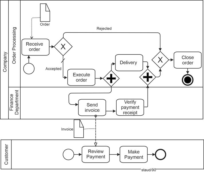
|
|
Figure 8.3-1: Order processing - Variant 4
Source: Adapted from [OMG 2009a, p. 104, Figure 10.12] and [OMG 2011, p. 269, Figure 10.85] |
|
Enthaltene Elemente - zusätzlich zur vorigen Abbildung:
- Becken
- Bahn
- Nachrichtenfluss |
|
8.4 A Public Business Process |
|
The BPMN authors understand public business processes to be those that take place between an internal business process and an external one. As previously noted, communication with external partners in BPMN is not modeled as a sequence flow, but rather as an exchange of messages - as illustrated in the following example. In this example, the patient is represented as a pool without activities. This is permissible in BPMN: message flows to or from such a participant in the business process start and end at the boundary of the pool. |
|
Apart from that, the example should be self-explanatory. |
|
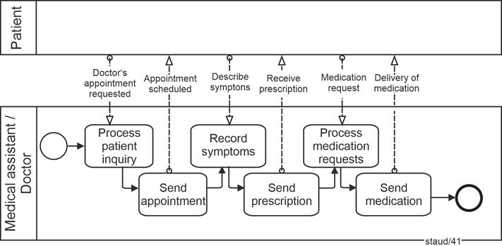
|
|
Figure 8.4-1: Contact between doctor's office and patient - Version 1
Source: [OMG 2011, p. 24, Figure 7.2] |
|
Elements included:
- Pool
- Pool with public process
- Start event
- Tasks
- Message flows |
|
8.5 Collaboration |
|
A collaboration describes the interactions between two or more participants in the process, each of whom is usually represented by a separate pool. Between these participants, only the exchange of messages can occur, merging the pools or the objects within them. |
|
When public processes are involved, the activities used for collaboration can be regarded as the points of contact between the participants. The corresponding internal processes may contain much more internal detail than what is shown in the public process. A pool may also remain empty as a "black box," as shown earlier. |
|
The following figure, based on the previous example, illustrates this elaborated process on the patient's side and the exchange of messages between individual activities. When, as in this case, two or more public processes communicate with each other, the BPMN authors refer to this as a global process. In such a process, message flows occur between pairs of activities belonging to the respective business processes. [OMG 2011, pp. 24f] |
|
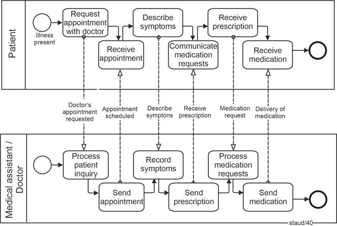
|
|
Figure 8.5-1: Contact between doctor's office and patient - Version 2
Source: [OMG 2011, p. 25, Figure 7.3] |
|
Elements included:
- Start event
- Task
- End event
- Message flow
- Public business process
- Messages between processes |
|
|
|
|
|
Interim remark
The examples above should have made the potential of the BPMN method clear, so that detailed explanations of the method elements and syntax can now follow. Accordingly, the following section provides a summarized discussion of activities, data objects, events, control flow, and gateways. Detailed descriptions can be found in the original sources ([OMG 2013] and [Staud 2024]). |
|
|
|
9 BPMN - Process steps |
|
|
|
9.1 Activities |
|
The individual actions into which the overall process is divided during process modeling are referred to in BPMN as activities. This use of the term is unrelated to the identically named concept in UML. It corresponds to what is called a function in Event-driven Process Chains and an action in UML activity diagrams. As also noted earlier, a BPMN activity is represented in diagrams by a rectangle with rounded corners. |
|

|
|
Abbildung 9.1-1: Graphical representation of activities |
|
The BPMN authors define activities as work performed within a business process. This somewhat vague definition is clarified by specifying that an activity can be either atomic (elementary) or non-atomic, and by indicating the levels on which activities can occur. These are three ([OMG 2011, p. 151]): |
|
- Tasks
- Subprocesses
- Processes
|
|
Activities are therefore the executable elements of a BPMN process. Sequence flows lead to and from an activity. If several flows converge toward or diverge from an activity, their internal structure can be clarified through an operator (gateway), as is generally customary in process modeling (cf. below and in [Staud 2024, Chapter 11]). |
|
If several sequence flows enter an activity without a gateway, the BPMN authors refer to this as an uncontrolled flow. In such cases, the following applies: When a token arrives, the activity is started. If another token arrives, a new instance of the activity is initiated. |
|
9.2 Tasks |
|
At the lowest level are the tasks, which are described as atomic. They represent elementary activities that, in the given context, are not further subdivided. The choice of terminology highlights the inherent subjectivity of this distinction, which of course remains here as well. |
|
Definition: Task (BPMN) |
|
A task is an atomic activity within a process flow. It is used when the activity cannot be further detailed. ([OMG 2011, p. 156]) |
|
Tasks are performed either by end users (actors within the process) or by application programs, with or without the use of AI techniques. This does not imply a strictly Tayloristic level of granularity, but rather one that focuses on elementary operations - for example, perform calculation rather than prepare offer. However, this approach does not eliminate the somewhat arbitrary nature of such distinctions (see also [Staud 2019] and [Staud 2014]). |
|
9.2.1 Variants |
|
Three variants concerning the internal structure of tasks can be indicated by graphical markers: |
|
- Tasks with a loop character are marked with a loop marker.
- Tasks that can be executed multiple times in parallel (i.e., where several instances can be started simultaneously) are marked with a multi-instance marker.
- Tasks that serve as replacements for others ("for compensation") are marked with a compensation marker.
|
|
The following figure shows the graphical representation of these marker elements. |
|
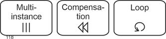
|
|
Figure 9.2-1: Three variants of tasks - multi-instance, compensation, loop |
|
Multi-Instances |
|
Some tasks can be restarted without waiting for the completion of previous ones - that is, they can occur in parallel. Take, for example, the dispatching of parcels by an online retailer. Such a task is marked as multi-instance/parallel. This marker consists, as shown above, of three vertically aligned lines. |
|
If a task allows multiple instances, but they are started one after another (sequentially), it is marked as multi-instance/sequential. This marker consists of three horizontally aligned lines. |
|
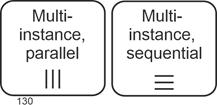
|
|
Figure 9.2-2: Graphical representation of tasks - multi-instance markers |
|
The multi-instance marker can also be combined with the compensation marker. The number of instances may be calculated or derived from data. What matters is that another instance can be started without waiting for a previous one to finish. |
|
Compensations |
|
For certain tasks, the model specifies what should happen if execution fails - that is, the task refers to another task that is to be executed in case of failure. This referenced task carries the compensation marker. |
|
Such a situation could, of course, also be modeled using a subsequent Exclusive Gateway with "failed" as one option, but referring directly to a compensation task is more elegant (and more compact in the model). |
|
In total, two tasks are involved in a compensation: one in which a compensation event captures the case of failure, and another that defines the compensation task. A sequence flow exists between the two, though it is not shown graphically. For a graphical example, see [Staud 2024, Section 10.6]. |
|
An example would be making a hotel booking through an online portal. If it fails, one must book directly by phone as a substitute. This substitute booking represents the task with the compensation marker. |
|
Tasks with Loop Character |
|
In many business processes, there are tasks that must be repeated. These are tasks that are performed one after another - that is, when one is completed, the next begins. Examples include calling suppliers about a desired delivery or processing incoming emails in the morning. Tasks of this kind receive a loop marker, making their iterative nature immediately visible in the model. |
|
The loop is defined by a Boolean expression and is repeated as long as the condition evaluates to true. For example: All emails processed (Y/N)? |
|
This situation could also be modeled as an explicit loop in the sequence flow (see [Staud 2024, Section 10.5]), provided the task is decomposable. However, for elementary tasks, the solution presented here is preferable, as it avoids unnecessary decomposition and is space-efficient. |
|
Also for Subprocesses |
|
The markers described above also apply to subprocesses (see the next section). They have essentially the same meaning, except that this section refers to individual tasks, whereas subprocesses represent short process segments. |
|
For example, in the case of a loop marker: a task might be processing incoming emails, while a subprocess could be shipping parcels. The latter consists (at a corresponding level of aggregation) of several activities that must be repeated continuously. |
|
9.2.2 Task Types |
|
In BPMN, several types of tasks are distinguished. This classification, and the corresponding graphical markings, relate to the following aspects: |
|
- The degree of human involvement
- The degree of software participation in task execution
- The orientation toward message exchange
|
|
The first two aspects help indicate the level of automation, where automation refers to the automatic execution of activities by programs or machines. |
|
All task types are represented, as shown earlier, by a rounded rectangle with a single thin solid outline. Each task type is identified by a specific graphical symbol in the upper left corner of the rectangle. A task without a type is referred to as an abstract task. |
|
Manual Task |
|
Despite increasing automation, business processes still include tasks that must be carried out manually - and this applies not only to decision-making processes. BPMN distinguishes two types of human-performed tasks: manual work (manual task) without software support, and user-performed work (user task) with the aid of an application program. Recent developments in robotics and individualized automated production suggest that, as such technologies become integrated into typical business processes, new modeling elements will likely be required. |
|
A manual task represents an activity not executed by a business process engine or an application program - for example, a telephone technician performing work based on a paper instruction [OMG 2011, p. 163]. It is identified by a hand icon. |
|

|
|
Figure 9.2-3: Graphical representation of tasks - manual task |
|
User Task |
|
A user task is carried out by a person with the aid of an application program. The execution of such a task is managed by a task list manager. Its graphical marker depicts the upper half of a human figure. |
|
A user task can be implemented in various ways, for example, through web service technologies. |
|

|
|
Figure 9.2-4: Graphical representation of tasks - user task |
|
Service Task |
|
A service task involves the use of a service during execution, such as a web service or an automatically running application program. Its graphical marker consists of two interlocking gears. |
|

|
|
Figure 9.2-5: : Graphical representation of tasks - service task |
|
Send Task |
|
A task dedicated to sending a message is called a send task. It concerns messages directed to an external process participant. The graphical marker is a filled envelope, corresponding to the symbol used for a message event (throwing). |
|
After the message has been sent, the task is considered complete. |
|

|
|
Figure 9.2-6:Graphical representation of tasks - send task |
|
Receive Task |
|
A receive task is used for situations in which a message from an external process participant must be awaited. It can also be used to start a process, if that process is triggered by a message. The graphical marker is an unfilled envelope, consistent with message (catching) events (see Section 9.2.2). After the message is received, the task is complete. |
|

|
|
Figure 9.2-7: Graphical representation of tasks - receive task |
|
Process Start Task |
|
To indicate that a process is started by a message from an external participant, the process start task is used - a receive task combined with an event symbol. The event type is message / start event / catching (see [Staud 2024, Section 9.2.2]). |
|

|
|
Figure 9.2-8: Graphical representation of tasks - process start task |
|
See also [Staud 2024, Section 12.1], where the process start pattern is discussed. |
|
Business Rule Task |
|
A business rule task provides input to a business rules engine and receives the resulting output. Thus, it both sends and receives data. Its graphical symbol, shown as a simplified table in the upper left corner, is illustrated in the following figure. |
|
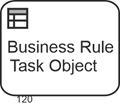
|
|
Figure 9.2-9: Graphical representation of tasks - business rule task |
|
Script Task |
|
A script task is executed by a business process engine. The modeler or developer writes a script in a language interpretable by the engine. Once the task becomes active, the script is executed, and upon completion of the script, the task itself is considered complete. The graphical marker is a curved document icon representing a written page. |
|
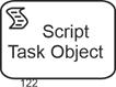
|
|
Figure 9.2-10: Graphical representation of tasks - script task |
|
Global Task |
|
Global tasks contain reusable elementary task definitions that can be invoked by any process via a call activity (see Section 6.2). The following task types can be defined as global: |
|
- Global user task
- Global manual task
- Global script task
- Global business rule task
|
|
Their graphical representation is the same as for the respective task types above, but with a bold border. |
|

|
|
Figure 9.2-11: Graphical representation of tasks - global user task |
|
9.3 Subprocesses |
|
9.3.1 Expanded or Collapsed |
|
Subprocesses are represented by a graphical symbol similar to that used for tasks. They describe a set of work steps that belong together from a process perspective. When these steps are shown graphically, the subprocess is called expanded; otherwise, it is called collapsed. The distinction between expanded and collapsed refers solely to the form of representation. |
|
A subprocess is a sequence of activities, gateways, events, and sequence flows that is contained within a parent process. The definition is as follows: |
|
Definition: Subprocess |
|
A subprocess is a compound, decomposable activity that is contained within a process. ([OMG 2011, p. 173]) |
|
The essential point is that subprocesses are invoked as a whole rather than through the individual activities they contain. |
|
A subprocess may be shown either by a single labeled symbol (collapsed) or as an internal process within a frame (expanded). The graphical representation of a collapsed subprocess is the same as for tasks but includes a plus sign inside a small square. This indicates that the symbol represents a subprocess rather than a task. The figure below provides an example. |
|
|
|
Figure 9.3-1: Representation of a collapsed subprocess |
|
A subprocess can also be shown with all modeling elements inside a frame. This form is called an expanded subprocess. As with collapsed subprocesses, expanded subprocesses are connected to the remainder of the process via sequence flows. In the figure below, this is suggested through the arrows at the sides. |
|
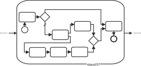
|
|
Figure 9.3-2: Representation of an expanded subprocess |
|
Motivation |
|
A subprocess contains logically related segments of work that can be clearly delineated. A characteristic feature is that these segments may be invoked only as a whole from the parent process, though in various ways (as shown below). This modeling element exists in some form in all process-modeling methods. |
|
One motivation is the need to represent multiple levels of modeling detail. On the one hand, there is the standard process level; on the other, a level in which individual tasks are described in more detail. In such cases, it is useful to encapsulate these more detailed descriptions in a subprocess. |
|
A more presentation-oriented motivation, particularly for collapsed subprocesses, is the desire to collect frequently occurring process fragments into a collapsed subprocess and show them only once, in detail, elsewhere in the process landscape. This improves clarity and corresponds to what is generally referred to as encapsulation. |
|
Using subprocesses also allows different modeling layers to be displayed, becoming increasingly detailed from top to bottom. Such representations help users gain an overview of a complex process model. |
|
Additional BPMN-specific motivations arise from the mechanisms of invocation. For instance, when a process fragment is intended to be triggered by an event, BPMN provides event subprocesses. |
|
9.3.2 Variants |
|
As with tasks, subprocesses may have variants that are indicated by graphical markers: |
|
- Subprocesses with looping behavior: a thin, segmented circular line with an arrowhead
- Subprocesses with parallel execution: multi-instance markers, either parallel or sequential, with three vertical or horizontal lines
- Subprocesses for compensation: two triangles pointing left
- Ad hoc subprocesses: a tilde
|
|
A subprocess may have more than one such characteristic. In that case, all markers belonging to a subprocess are grouped together and centered along the lower inner edge of the subprocess frame. |
|
Loops |
|
A collapsed subprocess with a loop marker indicates that the internal activities have a looping character and are executed repeatedly in sequence. Such situations occur frequently in process modeling. Any repetitive work pattern in which the internal loop is not explicitly modeled can be represented in this way - for example, conducting a series of interviews or processing incoming email. |
|
Here, the subprocess marker is combined with the loop marker. |
|
|
|
Figure 9.3-3: Representation of a collapsed subprocess with looping behavior |
|
This type of loop must not be confused with a loop modeled explicitly in the sequence flow (a backward jump to an earlier part of the process). In such cases, the loop is shown directly in the process model. See [Staud 2024, Section 10.5]. |
|
Multi-Instance Subprocesses |
|
A collapsed subprocess with a multi-instance marker indicates that the subprocess may have multiple instances that can start in parallel or sequentially. This results in two subprocess types: |
|
- Multi-instance subprocess (parallel)
- Multi-instance subprocess (sequential)
|
|
|
|
Figure 9.3-4: Representation of a collapsed subprocess with parallel or sequential multi-instance behavior |
|
The motivation for these elements is to describe complex process behavior realistically. |
|
The simplest way to imagine the process flow is that one instance is started and completed, and only then - if necessary - the next instance is started. In reality, however, most processes allow multiple instances to be started either simultaneously (parallel) or one after another (sequential). This applies to non-automated process segments, provided capacity is available, just as much as it does to automated ones. |
|
These modeling elements allow such situations to be expressed. Examples include handling multiple incoming orders simultaneously (parallel) or shipping deliveries sequentially because only one shipment can be prepared at a time, though many shipments must be carried out throughout the day. This could also be modeled by repeatedly restarting the process or by an explicit process loop (see [Staud 2024, Section 10.5]). |
|
Compensation Subprocesses |
|
A compensation subprocess serves as a replacement for another subprocess if the latter fails. Consider the following situation: A hotel reservation made through an online portal is modeled as a subprocess. If the reservation fails, the fallback is to book by telephone via a travel agency. This fallback is modeled as the compensation subprocess. The marker consists of two triangles pointing left. |
|
|
|
Figure 9.3-5: Representation of a collapsed subprocess with compensation |
|
Ad hoc - Collapsed |
|
In BPMN, ad hoc refers to process segments that cannot or should not be arranged in a sequence flow. Such cases do occur in business processes: |
|
- Creative work, such as developing a strategy for a product launch or preparing a book chapter (developing content, creating graphics, resolving references, writing text, integrating graphics, editing, etc.)
- Integration of non-standardized processes into a process model (for whatever reason)
|
|
Such workflows are, without abstraction, very difficult to model using simple sequence flows. Here, to abstract means, for example, that instead of modeling all individual tasks of a large project, the entire project is represented as a single task - for instance, "Create technical book" instead of develop subject matter, produce graphics, check references, write text, embed graphics into the text, edit text, and so on. |
|
An ad hoc subprocess in the BPMN sense has a well-defined set of activities, but no defined sequence flow. This may be because the sequence is unknown or cannot (or should not) be determined. The BPMN authors emphasize the "cannot": "... and cannot be defined beforehand" [OMG 2009, p. 128]. |
|
During execution, the activities of an ad hoc process are performed spontaneously, in a spontaneous order. |
|
In a Business Process Diagram (BPD), the activities of an ad hoc subprocess are separate. During execution, any of them may become active in almost any order and frequency. An attribute (AdHocOrdering) specifies whether activities must be performed in parallel or sequentially; the default is parallel. A second attribute, AdHocCompletionCondition, specifies the condition under which the process ends. |
|
The marker for ad hoc subprocesses is a tilde. |
|
|
|
Figure 9.3-6: Representation of a collapsed ad hoc subprocess |
|
Ad hoc - Expanded |
|
If an expanded ad hoc process is used, the involved activities are placed within a rectangle with rounded corners. The following figure shows an example. No sequence flow is specified. However, the fact that the BPMN authors nevertheless consider information flows and even individual sequence flows to be modelable in this context is illustrated by the continuation of this example in Figure 10.3-6. |
|
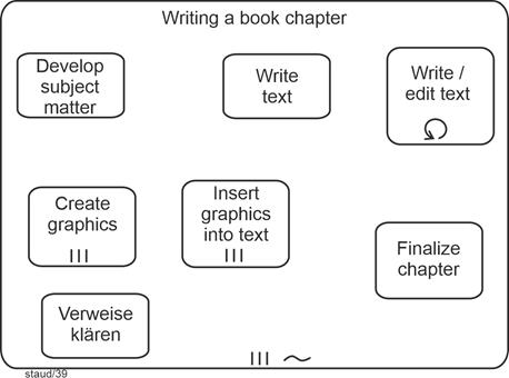
|
|
Figure 9.3-7: Expanded ad hoc subprocess Writing a book chapter. Source: Adapted from [OMG 2011, p. 182, Figure 10.37] |
|
Elements included:
- Expanded subprocess with multi-instance (parallel)
- Task without marker
- Task with multi-instance (parallel)
- Task with loop marker |
|
The BPMN authors also list software development (at a lower level) and sales support as examples of ad hoc processes. |
|
The following restrictions apply to the use of theoretical elements in ad hoc subprocesses: |
|
- The following must be present: activities.
- The following may be present: data objects, sequence flows, associations, groups, message flows (as source or target), gateways, and intermediate events.
- The following must not be present, among other things: start events, end events, and choreography activities.
|
|
The BPMN authors note that it is challenging for a "BPM engine" to track the status of ad hoc processes. Such processes are typically supported by groupware applications. |
|
Eventually such a process ends. This is determined by evaluating an end condition that checks process attributes that have been updated by activities in the process. |
|
Multiple Markers |
|
The figure above shows a subprocess with more than one marker. The ad hoc subprocess (tilde) is also a parallel multi-instance subprocess. That is, the writing of a book chapter occurs in parallel with other chapters. Such combinations of markers are possible in various ways. In principle, a collapsed subprocess may have up to three additional markers besides its collapsed marker. All combinations are possible except one: a subprocess cannot simultaneously be a loop subprocess and a parallel multi-instance subprocess. The next figure shows all possible combinations. |
|
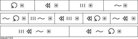
|
|
Figure 9.3-8: Possible combinations of subprocess markers |
|
The following example shows a subprocess with multiple markers. In the context of preparing a technical book, where the internal structure is not to be represented by sequence flows, the repetitive character of the work is indicated by the loop marker. |
|
|
|
Figure 7.3-9: Combinations of subprocess markers - loop and ad hoc structure |
|
9.3.3 Why use subprocesses? |
|
In general terms, the main reasons for using subprocesses are as follows: |
|
|
(1) Subprocesses make it possible to represent frequently occurring process segments in detail only once, while referring to them elsewhere in the model. This keeps process models more manageable. In BPMN, this is done by means of collapsed subprocesses.
|
|
|
(2) They make it possible to incorporate more detailed sections of a process into the overall model. This corresponds to what is discussed in [Staud 2024] and in even greater detail in [Staud 2014] under the heading "process modeling vs. function modeling." Normally, the level of aggregation in a process model is uniform across the entire process. A subprocess allows the modeler to capture, for example, both the main business process (providing a service from customer request to delivery) and the detailed modeling of individual tasks (such as calculating quotation line items).
|
|
|
(3) They support vertical modeling, in which different levels of aggregation are represented. Subprocesses can be used to create a link between two (or more) modeling levels. A lower-level process segment can be connected to a task at a higher level, turning the latter into an embedded subprocess.
|
|
Further Reading |
|
In [Staud 2024], you will find in-depth information on sub-processes for the following topics: |
|
- Embedded and referenced sub-processes
- Reusable sub-processes (call activities)
- Event sub-processes
- Transactions
- Call activity
- Event sub-processes
- Transactions
|
|
|
|
10 BPMN - Information and its processing |
|
|
|
10.1 Data and information |
|
Information is required, generated, processed, and possibly deleted in every business process, which is why it must also be addressed in the BPMN method. The BPMN authors refer to the information that plays a role in the business process as data objects. They view them as follows: |
Data Objects |
- Data objects provide information about what the process does, how documents, data, and other objects are used and updated in the process.
- They provide information about what activities need for their implementation and/or what they produce.
- They have no direct influence on the control or message flow [OMG 2009, page 19].
|
|
Data objects are represented in business process diagrams by four elements [OMG 2011, p. 27]: |
|
- Data object
- Data input
- Data output
- Data store (Collection)
|
|

|
|
Figure 10.1-1: Representation of the model element data object |
|
This method element, data object, is used to describe information that is required or generated by activities. Data input and data output perform the same function for processes. |
|
For data objects, it is also possible to specify their state: checked, rejected, etc. This is done in square brackets below the graphic symbol. See the examples below and in [Staud 2024, Chapter 14]. |
|
Data store |
|
The data store is selected for information that is to be retained beyond an instance (of the business process). It can therefore be used to represent databases and files of all kinds. |
|

|
|
Figure 10.1-2: Representation of the model element data store |
|
10.2 Associations |
|
In general, the linking of text and non-flow elements with flow objects is called an association. This also applies to the linking of data objects with flow objects. Such associations are represented as dotted lines, directed or undirected, i.e., with or without an open arrowhead. See the examples below. |
|
The link is necessary because actions are usually associated with data. They are created, processed, or deleted as part of activities. Therefore, data objects must be linked to the respective action through associations. For a graphical representation, see the following figure. |
|
Definition Association |
|
An association is a link between a flow object and a data object. |
|
The specific design of the integration of data objects into process models is described in the next section. |
|

|
|
Figure 10.2-1: Representation of a directed association |
|
Associations for artifacts |
|
Associations are also used to link artifacts to the business process, e.g., text annotations. They consist of an undirected association and the text annotation, in the graphical form shown below. There is always a need for textual additions in a process model. These can be content additions or process elements that cannot be mapped with the method, e.g., specific organizational assignments (as in the following figure). |
|
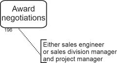
|
|
Figure 10.2-2: Artifact Text annotation |
|
10.3 Data in the business process |
|
Data or information is transported in every business process. This can be modeled directly or indirectly. Directly, by explicitly modeling the transport of information. Then there is, for example, a model element labeled "Transport CAD documents to the archive." Indirectly, simply by ensuring that the information reappears in the next activity where it is needed. |
|
Here, we will focus on direct transport. The following is possible in BPMN: |
|
- Data transport along a sequence flow.
- Simple data transport, which can even exist without a sequence flow (i.e., it models the cohesion of the process).
- Emerging information, i.e., a data object is created in a task.
- Incoming information, i.e., the data object is required in the task.
|
|
The following figure shows an example of an undirected association that connects a data object with a sequence flow edge. |
|
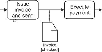
|
|
Figure 10.3-1: Association of data object with sequence flow edge |
|
Data transport via association is used to model simple data transport. The situation is as follows: Information is generated in one activity and sent to the next, where it is processed. In the graphical representation, a directed association is used for this, as shown in the following figure. |
|
The meaning is as follows: |
|
- The data object is created in the sending activity.
- In the receiving task, the data object flows into the work where it is needed.
|
|
As the example shows, there can also be multiple recipients. This type of graphical design therefore expresses not only the creation and transport, but also the use in the target activity |
|
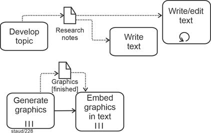
|
|
Figure 10.3-2: Data transport using association
Source: two fragments from Figure 8.3-6 |
|
It is also possible to model data transport parallel to the sequence flow. Here, as shown in the example in the figure above, it is explicitly stated that one activity must take place before the other. |
|
The creation of a data object or its processing (without the intention of transport) can also be expressed graphically, as shown in the following figure. There is then a directed association from the activity to the data object. |
|
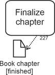
|
|
Figure 10.3-3: Data transport by means of association
Source: Fragment from Figure 8.3-6 |
|
The BPMN authors also stipulate that a business process can be started by a data object. In this case, an association is created from the data object to the activity. Several activities can also be triggered, so there may be an implicit AND operator. |
|
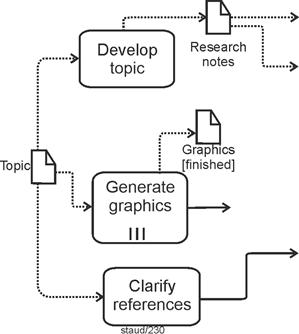
|
|
Figure 10.3-4: Start of a business process by a data object
Source: Fragment from Figure 8.3-6 |
|
In practical BPMN modeling, the direct modeling of data transport is often omitted. The data object then simply reappears in a subsequent downstream activity, usually with a changed state. As in the following example, where an invoice received must be countersigned before payment. |
|
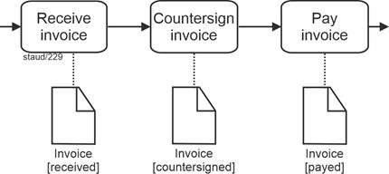
|
|
Figure 10.3-5: Data transport without explicit transport |
|
Here is the example as a whole. It shows a mixture of information and sequence flows, with a clear predominance of the former. For a list of model elements, see the box after the figure. |
|
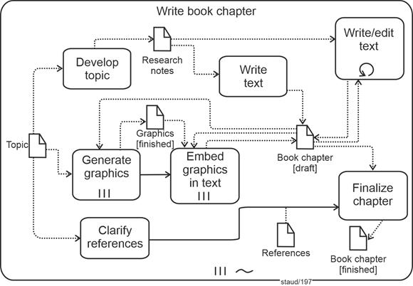
|
|
Figure 10.3-6: Unfolded ad hoc subprocess Writing a book chapter with data and sequence flows.
Source: Adapted from [OMG 2011, p. 183, Figure 10.38]. |
|
Process fragment:
- Unfolded ad hoc subprocess with multiple instances (parallel). The model assumes that work is being done on several chapters at the same time.
Elements included:
- Ad hoc marker
- Ad hoc subprocess
- Aggregation
- Association
- Association, directed
- Loop task
- Tasks
|
11 BPMN - Events |
|
|
|
11.1 Concept |
|
Events play an important role in BPMN. They are defined as follows: |
|
Definition: Event |
|
"An event is something that happens during the execution of a business process. Events influence the process flow and typically have a cause or an effect. ... However, the use of events is restricted to those that affect the sequence or timing of activities" [OMG 2011, p. 83] |
|
The definition draws on the general concept of properties, which is understandable. The restriction to events that affect the process flow makes sense. |
|
It is like in "real life." Some events are generated by us ("I quit my job"), while others affect us from outside ("I was fired"). Accordingly, events in BPMN are considered in two ways: |
|
- First, as events that are generated in the business process and then have an effect there or externally.
- Second, as events that affect the business process from outside.
|
|
The points in the business process that can receive (catch) or send (throw) such events are modeled. More on this below. A method element inserted into the process model for this purpose can only represent one or the other. We must therefore separate the actual event ("stock level has fallen below reorder point," "calculation is complete") from the method element event. When modeling, we must then decide whether the method element should receive events from the process environment or send them to it. |
|
It therefore concerns the scope of influence of events, which will be referred to here as the event space. The BPMN authors have specified the following: |
|
- Events can be received from the application area in which the process takes place.
- Events can be sent to the same process or subprocess, and in the case of subprocesses, also to the higher-level processes, which the BPMN authors refer to as parent processes. This is discussed below for the individual event types.
|
|
It is clear from the BPMN authors' explanations that this part of the method is of great importance. In standard process modeling, this would not be necessary to this extent, but when it comes to implementing the process model in executable software, it is indispensable. |
|
The BPMN authors cite the following abstract examples of events [OMG 2011, p. 83]: |
|
- Start of an activity
- End of an activity
- Change to a document
- Incoming message
|
|
The above corresponds to the standard definition of events. However, the following distinction between three types of events, which is based on the section of the process in which the events occur, goes further: |
|
- Start events
- Intermediate events
- End events
|
|
Start and intermediate events have triggers. End events can have results that arise from the business process. |
|
Graphical representation |
|
The basic graphical representation is that of an empty circle in which markers for the specific event can be placed. More on this below. |
|

|
|
Figure 11.1-1: Representation of an event - general form |
|
11.2 Differentiation |
|
The BPMN authors differentiate between events in a variety of ways, and all of these distinctions are also expressed in the graphical representation. The starting point for differentiation is the distinction between start, intermediate, and end events, as already introduced above. They are represented graphically with black lines and are otherwise as follows: |
|
- Start events are drawn with a single thin line
- Intermediate events are drawn with two thin lines
- End events are drawn with a thick line
|
|
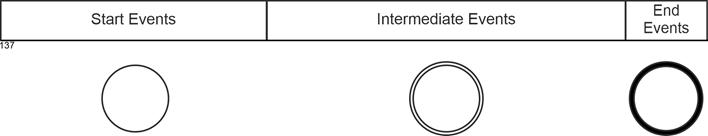
|
|
A distinction is then made between whether the trigger of the event is catching or throwing. Together with the specification that start events are only catching triggers, end events are only throwing triggers, and intermediate events have both, this results in the header of the following figure. Message was chosen as an example of an event type (see section 9.2.2). |
|
Catching and throwing |
|
Catching means that ... |
Definition |
- ... there is a process element in the real business process that can perceive events.
- ... there is a process element in the process model that expresses this.
|
|
Perception refers to a specific context of the process model. This event space is defined by the business process, subprocesses, or other divisions. |
|
In terms of methodology, the ability to receive a trigger (which communicates the event) is realized by the so-called EventDefinition. Only with this can the trigger be received (the event perceived). If there are several receiving events at one point, there must also be several EventDefinitions. |
|
Throwing means that ... |
|
- ... in the real business process, there is a process element that generates events and makes them known to the event space.
- ... in the process model, there is a process element that expresses this.
|
|
[OMG 2011, p. 275]. |
|
How this is implemented in the real process (or how it exists there) depends on the circumstances. If the process has already been implemented in software, a software solution must be implemented for receiving and sending events. If the process is implemented by humans at the respective point, suitable structures must be set up for this purpose, e.g., communication systems. |
|
The following applies to the graphic design: For events that receive, the labels are not colored. For events that send, they are colored black. |
|
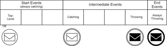
|
|
The third criterion covers special situations for subprocesses or tasks that are triggered by events. These events either start an event subprocess or trigger other tasks from a task. Graphically, they are then located on the boundary line of the triggering task. |
|
These events in the subprocess or in a task either interrupt the higher-level process (from which the call came) or the higher-level task, or they do not. This can also be expressed graphically. A dashed border line means non-interrupting, a solid line means interrupting. |
|
They exist as start and intermediate events. For start events, these are "event sub-process, interrupting" and "event sub-process, non-interrupting." For intermediate events, the variants are "boundary line, interrupting" and "boundary line, non-interrupting." In summary: |
|
- Start event / event sub-process, interrupting
- Start event / event sub-process, non-interrupting
- Intermediate event / boundary, interrupting
- Intermediate event / boundary, non-interrupting
|
|
The cumbersome nature of the designation stems from the complexity of the subject matter. Using the example of messages again, this results in the following final version of the header for the table below. |
|
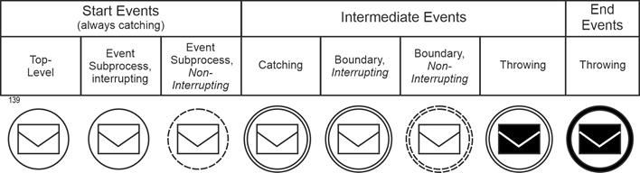
|
|
Event Trigger |
Event trigger |
The fourth differentiation is based on the triggers of the events. The following are available (the numbers refer to the figure below): |
|
|
1. No specific trigger (none).
|
|
|
2. Message with a MessageEventDefinition: This means that a message is expected or sent by a participant in the process. Graphic symbol: envelope.
|
|
|
3. Error with an ErrorEventDefinition: This symbol indicates that a named error message is generated. Graphic symbol: lightning bolt.
|
|
|
4. Timer with a TimerEventDefinition: This indicator can be used to express that the event captures time aspects. Graphic symbol: clock.
|
|
|
5. Escalation with an EscalationEventDefinition: This describes that a process situation has come to a head and special measures must be taken. Graphic symbol: upward-pointing arrowhead.
|
|
|
6. Signal with a SignalEventDefinition: Indicates that signals are being sent or received. Graphic symbol: triangle.
|
|
|
7. Cancel with a CancelEventDefinition: This label creates an event type that cancels the business process or the respective flow. Graphic symbol: slanted cross.
|
|
|
8. Compensation with a CompensationEventDefinition: If an event is marked as compensation and this event is attached to the boundary line of an activity, there must also be a sequence flow arrow to another activity. In the event of a crisis, this other activity then replaces the initial activity (the one with the compensation event). Graphical symbol: "Rewind button," as used on cassette recorders in the past.
|
|
|
9. Conditional with a ConditionalEventDefinition: For events that can be described by conditions, e.g., "Stock level has fallen below the reorder mark." Graphical symbol: Described sheet of paper.
|
|
|
10. Link with a LinkEventDefinition: An event with the label "link" indicates that two sections of a process are linked. Graphic symbol: right-pointing arrow.
|
|
|
11. Terminate with a TerminateEventDefinition: An event with this label signals the end of the process. Graphic symbol: filled circle.
|
|
|
12. Multiple with a multiple EventDefintion: This means that several triggers are assigned to the event. Graphic symbol: pentagon.
|
|
|
13. Parallel multiple. Same as "Multiple," except that all triggers must be active. Graphic symbol: horizontal cross.
|
|
For each trigger except for the false alarm ("None"), there is the above-mentioned marker in the graphical representation. This is placed in the event symbol. All markers are graphically designed so that a non-blackened and a blackened version are possible (see criterion 2 above). |
|
The following figure presents all event types together with their graphical representations. A detailed description of the triggers, including their relation to the event types and the nature of the trigger, is provided in [Staud 2024, Section 9.2]. |
|
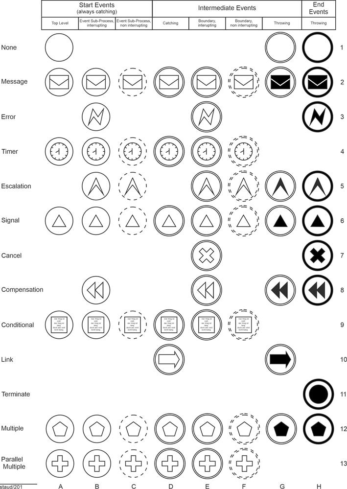
|
|
Figure 11.2-1: All event types with their identifying symbols
Source: Adapted from [OMG 2011, Chapter 10.4] |
|
The figure also shows that not all markers occur in all event types. Further details can be found in [Staud 2024, Chapter 4]. |
|
|
|
12 BPMN - Control Flow, Sequence Flow |
|
|
|
12.1 Introduction |
|
Business processes have a control flow. It specifies the process structure, and without it there can be no recording, penetration, or modeling. However, the authors of [OMG 2009] prefer the term sequence flow to control flow and define it as follows: |
|
Definition: Sequence flow |
|
Sequence flow shows the order in which activities are processed in a process or choreography [OMG 2011, p. 34] |
|
The BPMN authors give the following reason for not using the term control flow: |
|
BPMN does not use the term "Control Flow" when referring to the lines represented by Sequence Flow or Message Flow. The start of an activity is "controlled" not only by Sequence Flow (the order of activities), but also by Message Flow (a message arriving), as well as other process factors, such as scheduled resources. Artifacts can be associated with activities to show some of these other factors. Thus, we are using a more specific term, "Sequence Flow," since these lines mainly illustrate the sequence that activities will be performed [OMG 2009, p. 98]. |
|
It is therefore the meaning of message flow and other "controlling elements" that led to this definition. |
|
Another factor enters into this - implicitly, without being stated. The term control flow suggests, conceptually, that one action can direct another. If a department manager instructs the responsible employee to prepare a quotation for a customer request, he or she must comply. This is possible within a company, but not between different companies. When you place an order with another company, it is not obliged to accept it. Since BPMN is designed to capture processes that take place between companies or organizations as well, the choice of the term sequence flow was therefore the more appropriate one. |
|
12.2 Flows |
|
The BPMN authors distinguish between different types of flows: |
|
- Normal sequence flow
- Connections
- Ad hoc (no flow)
- Uncontrolled flow
- Flow with conditions
- Preset flow
- Flows for exceptions
|
|
Normal sequence flow |
|
This refers to the normal sequence flow, from the start event through the activities to a final event. As shown above, it is represented graphically by a line with a filled arrowhead. |
|
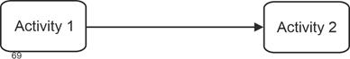
|
|
Figure 12.2-1: Representation of a sequence flow edge |
|
Exceptions are sections of the sequence flow that originate from an intermediate event of the types boundary line interrupting/non-interrupting [OMG 2011, p. 34]. |
|
Uncontrolled flow |
|
The BPMN authors define an uncontrolled flow as a sequence flow edge that is not subject to any conditions and does not pass through any operators. The simplest case is a sequence flow edge that simply connects two activities, as shown in the figure above. However, this also refers to a situation where several sequence flow edges lead to or away from an activity without a gateway. The rule here is that a token is released for each of these uncontrolled flows [OMG 2011, p. 34f]. This corresponds to an implicit AND link. The graphical representation is as shown above. |
|
Conditional flow |
|
A sequence flow can have conditions that are checked at runtime of the process (according to the authors' wording) to determine whether the branch becomes active/is used. If the branch comes from an activity, it is marked with a small diamond at the beginning of the line. See the following figure. |
|

|
|
Figure 12.2-2: Representation of a flow with a condition |
|
If the branch comes from an operator (gateway, see below), it does not receive a diamond. In this case, the normal arrow representation is used, as shown above. |
|
Default flow |
|
For data-based exclusive OR decisions or for inclusive decisions (more on this below), there is another sequence flow type, the default flow. This is only used if the others are not valid at runtime (literally!). For these sequence flow edges, a backslash is inserted at the beginning of the line. |
|

|
|
Figure 12.2-3: Representation of a default flow |
|
Flows for exceptions (exception flow) |
|
This flow type is used to process exceptions. It is always based on an intermediate event of the types Boundary line interrupting / not interrupting. It therefore occurs outside the normal flow. It is represented graphically by an intermediate event that is placed at an activity. When this event occurs, an arrow line indicates which activity is then triggered. |
|
The following figure shows an example: The activity is data center operation. The exception situation is flooding. Emergency management is then triggered. |
|
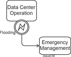
|
|
Figure 12.2-4: Representation of an exception flow |
|
Element included:
- Error intermediate event / boundary line, interrupting |
|
What does the above mean when an event is placed on the boundary line of an activity? It corresponds to an "IF query" to the activity. Something like this: |
|
- Has an emergency occurred?
- Have two weeks passed (in the case of a time query)?
- Is a replacement activity to be performed?
|
|
The IF query has two possible outcomes: yes or no. If the answer is yes, the event occurs and the sequence flow continues beyond the event. In the case of a negative response, the activity continues its other work (the "normal flow"). |
|
Without this process-related interpretation, it can also be seen as follows: The placement on the boundary line refers to the concept of the event space of the activity (the process). In this space, all possible events can occur, to which different responses are then given. |
|
13 BPMN - Gateways |
|
|
|
13.1 Basics |
|
As shown repeatedly above, a distinction must be made between the process model, which describes all possible paths through the business process, and an instance of the model, which records a specific path through the business process. This distinction is necessary here when explaining gateways because, as with instances, the process model must take into account all possible branches or merges that may occur in the individual instances. |
Instances |
Why gateways (operators)? |
|
In business processes, it can happen that the processes multiply (branch) at one point or that several come together (merge) because they then continue in a single flow. Such points are important and must be represented. |
|
Operators have been developed in process modeling for these situations, essentially the AND, OR, and XOR operators, which are used for branching and merging. BPMN also has these operators; they are called gateways here and are supplemented by a few additional variants. The gateways can now be used to clarify which situation applies... |
Operators, Gateway |
- when several flows (control or sequence flows) converge
- when several arise and are continued
|
|
This is the syntax-based view; the content-based view ("decisions, subtasks, conditions, ...") is considered in [Staud 2024, Chapter 12]. |
|
For example, the following situation exists: One edge (here: sequence flow branch) arrives at a gateway and several edges depart. This is a branch. |
|
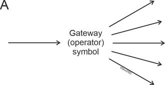
|
|
Figure 13.1-1: Branching sequence flow edges |
|
Or several edges arrive and one departs (B), which is also called a connection or merge. |
|
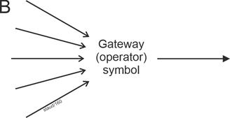
|
|
Figure 13.1-2: Merging sequence flow edges |
|
Or several arrive that are linked, and several branching ones depart. |
|
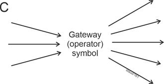
|
|
Figure 13.1-3: Merging and branching sequence flow edges |
|
In all three cases, it must be clarified what meaning (semantics) lies behind the branching or merging. |
|
Situation A |
|
Let us consider only the outgoing sequence flow branches (edges); incoming ones (one or more) should not play a role for the time being. Such a branch can have different causes: |
|
- The 2 to n edges located after the gateway become all active during the respective pass. In such a case, we refer to an AND operator, in BPMN a parallel gateway (see section 11.4) or a parallel event-based gateway (see [Staud 2024, section 11.5]).
- Exactly one of the outgoing edges becomes active during the respective pass. In such a case, we refer to an exclusive OR operator (XOR), or in BPMN, an exclusive gateway. In BPMN, this can be data-based (see [Staud 2024, Section 11.2]) or event-based (see [Staud 2024, Section 11.3]).
- At least one and otherwise any subset of the outgoing edges becomes active. In such a case, we refer to an OR operator, or in BPMN, an inclusive gateway.
|
|
The type of branching gateway is therefore determined by the semantics of the respective process section. A parallel gateway (branching) here means, for example, that several tasks are triggered at this point in the business process. We then also refer to subtasks. |
|
An exclusive gateway means that alternatives are available. This often involves decision-making situations, the outcome of which is modeled by the alternative control flows. This is a very common pattern in business processes. |
|
The inclusive gateway is usually less familiar. However, it does occur in regulations, rules, and laws. Here, situations in the business process are recorded in which at least one of the outgoing flows becomes active. The emphasis is on "at least," so any subset of the sequence flows can become active. |
|
A special feature of BPMN is the Complex Gateway. It describes situations in which the branch is not to be mapped with the other operators (see [Staud 2024, section 11.7]). |
|
Situation B |
|
Situation B describes the counterpart, so to speak: Several edges are merged ("fused"). The continuing sequence flows (one or more) are irrelevant here. |
|
Here, the gateway describes how the "incoming" control flows must be structured so that the flow continues via the gateway: |
|
- All (2 to n) edges must arrive before the flow can continue via the gateway. This is a parallel gateway.
- Exactly one edge must and may only arrive before the flow can continue. This is an exclusive gateway.
- At least one and otherwise any subset of several edges must arrive before the flow continues. In such a case, we refer to an inclusive gateway.
|
|
In their examples, the BPMN authors often omit the gateway for incoming sequence flows. They then refer to uncontrolled flow. Which gateway is implicitly present, so to speak, must be inferred from the process context. |
|
After many years of teaching process modeling, I can say that this is not recommended, especially at the beginning of the learning process. |
|
Situation C |
|
The case in which several edges arrive and depart at the same time can be traced back to the two cases above. The BPMN authors recommend using two gateways for this situation, one for converging and one for diverging [OMG 2011, p. 288]. |
|
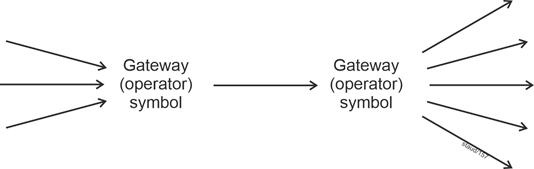
|
|
Figure 13.1-4: Diverging and converging sequence flow edges |
|
Event-driven or not |
|
Basically, the BPMN authors assume that the control flow in the gateways (the behavior of the tokens) is controlled by the data of the business process. This is also how the method is designed. This means that with the "normal" set of elements in the method, it is difficult to model situations in which the process flow is controlled by external events. For example, when an offer is sent out and the company waits for the response of the (potential) customer. For this reason, additional gateways have been introduced that are event-driven [OMG 2011, p. 297], which leads to the following distinction: |
|
- One group of gateways is controlled from within the process, from the data stored in it, i.e., the further course of action results from the process events. Due to the goal of "implementation in a BP engine," this leads to the formulation "evaluation of expressions using process data."
- The other group is controlled by messages from external participants in the process (or by temporal aspects) (see sections 11.3 and 11.5 in [Staud 2024]).
|
|
The distinction therefore aims to identify where the controlling information for the gateway comes from. |
|
Graphical representation of gateways |
|
Compared to UML, the BPMN authors wanted to simplify the graphical representation of operators/gateways. There is now only one basic graphical element that is used to represent all of them. This consists of an inverted diamond. |
|

|
|
Figure 13.1-5: Representation of a gateway |
|
13.2 Exclusive gateway - data-based |
|
The exclusive gateway describes branches based on alternative decisions. For each instance of the business process (each run), only one of the outgoing sequence flow branches becomes active. It can be data-based or event-based. Here is the data-based gateway first; the event-based gateway will be considered in the next section. |
|
The exclusive gateway can be represented by the basic symbol or by a basic symbol with an X added to it. |
|

|
|
Figure 13.2-1: Graphical representation of the exclusive gateway - data-based |
|
Of course, such a gateway should be defined in such a way that a sequence flow branch always becomes active during each pass through the process (each instance), i.e., one of the alternatives always occurs. Otherwise, the process could come to an undesirable standstill ("deadlock"). To avoid this under all circumstances, a sequence flow branch can be defined as default ("else branch") in BPMN. This becomes active if the others do not occur, i.e., if their conditions are not met. |
|
13.2.1 Branching |
|
In the branching case, there is a task followed by several possible continuing sequence flows with tasks, but only one of these becomes active in each instance. |
|
Abstract example |
|
First, an abstract example that illustrates the above explanations. Once task A1 has been completed, either task A2, A3, or A4 is performed. Furthermore, if A2 or A3 are not activated, task A4 is started. The slash on one of the sequence flow edges identifies the "else branch" introduced above. |
|
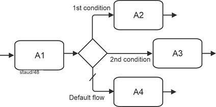
|
|
Figure 13.2-2: Data-based exclusive gateway - abstract |
|
A: Activity
Token
Based on the token concept, the exclusive gateway can also be described as follows: The incoming token is sent to exactly one of the continuing sequence flow branches. |
|
Content-based example |
|
The following figure shows a simple content-based example. After an order is received, a check is made to see whether the order can be accepted or not. One branch then leads to the task Accept order, the other to Reject order, and the third to Contact customer if there are any uncertainties and further information is required. |
|
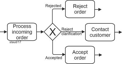
|
|
Figure 13.2-3: Order receipt with data-based exclusive gateway - branching |
|
13.2.2 Merging |
|
If alternative sequence flow branches arrive and need to be merged (e.g., because they continue in a single sequence flow afterwards), the exclusive gateway is also used. This means that there is a decision situation upstream, followed by tasks that are valid for all alternatives, which is why the sequence flows are merged again. |
|
Abstract example |
|
First, an abstract example. The exclusive gateway clarifies: A1, A2, and A3 are alternatives; one of the tasks must be solved, then A4 starts. |
|
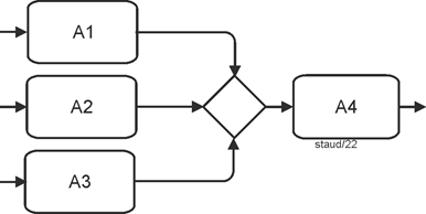
|
|
Figure 13.2-4: Data-based exclusive gateway - merging |
|
Sometimes you see business process diagrams that do not use the gateway symbol at this point. This reduces the informative value of the process model and should therefore be avoided. |
|
A: Activity
Reading note:
This fragment is correct ...
... if tasks A1, A2, and A3 are alternative and...
... if the same task (A4) continues afterwards.
Conversely, the following is also specified:
- Only one sequence flow branch may be active for each instance.
- One must also be active, otherwise there is also a modeling error. |
|
Content-based example |
|
The following example describes the situation in which an order was received that was either rejected or accepted, or in which the client had questions. Regardless of which case occurred, management is then informed. |
|
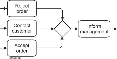
|
|
Figure 13.2-5: Order acceptance with a data-based exclusive gateway - merging |
|
Note:
Exactly one token arrives at the exclusive gateway, which is then forwarded. |
|
13.3 Exclusive gateway - event-based |
|
The event-based Exclusive Gateway describes a decision-making situation based on alternatives. However, in this case, they are based on events that affect the business process from outside the business process - in the process or as part of a choreography (see Chapter 13 in [Staud 2024]). These events are typically based on messages and their receipt. Other event types are also possible, e.g., timers. |
|
It is an XOR operator, which is why only one of the outgoing sequence flows becomes active for each instance; the others are then no longer valid. The gateway can be used in the middle of the process or at the beginning of the process. |
|
The graphical element is structured as follows: |
|
- As always, the basis is the gateway symbol, into which an event symbol is inserted.
- The event symbol either has a double line, which indicates a receiving intermediate event (interrupting), or a single line, which indicates a starting event.
|
|

|
|
Figure 13.3-1: Graphical representation of an event-based gateway - basic and for the start of the process |
|
Reminder:
The symbol in the middle indicates the event type Multiple. The double circle line indicates an intermediate event / receiving or boundary line, interrupting.
This establishes that at this point, the process waits for corresponding intermediate events (or start events), which then activate the sequence flow branches. |
|
Here, the decision is made by an event that occurs at the respective point in time in the process environment, in the informational environment or in the event space of the business process. Normally, this is communicated to "the business process" by the receipt of a message. This event determines which further sequence flow branch becomes active. The decision (which is articulated in the message) is thus made by another process participant [OMG 2011, p. 297]. |
|
13.3.1 Branching |
|
Event control is then modeled in such a way that the events are specified directly after the gateway. Three variants are possible: Specifying the event by ... |
|
- ... a recipient message
- ... a message event (as an intermediate event)
- ... a timer
|
|
Syntax |
|
The BPMN authors note the following regarding the syntax of the event-based exclusive gateway [OMG 2011, 297f]: |
|
- It must have at least two outgoing sequence flows
- The outgoing sequence flows must not have any conditions
- If message intermediate events are used, no tasks of the type receive may be used - and vice versa. There is a syntactic reason for this. A gateway cannot lead alternatively to a task with a message and to an event.
- Receive tasks used here must not have any attached intermediate events.
- Only the following triggers of intermediate events are permitted: message, signal, timer, condition, and multiple.
- Target elements of the gateway in such a configuration must not have any other incoming sequence flows, only the one from the gateway.
|
|
Examples |
|
The following examples correspond to those in the original source. They clearly illustrate the possibilities that the BPMN authors see here. The first contains two message events and one timer event in the outgoing sequence flow branches. |
|
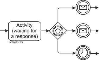
|
|
Figure 13.3-2: Example of an event-based gateway with message events and timer
Source: Slightly modified from [OMG 2011, Fig. 10.116, p. 298] |
|
Elements included (selection):
- Exclusive gateway / event-based
- Message intermediate event, receiving
- Timer intermediate event / receiving |
|
The second example contains two tasks of the type receiver in addition to the timer. Here, the controlling message reception is defined by the time constraint and two tasks that are activated by the message reception. |
|
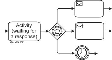
|
|
Figure 13.3-3: Example of an event-based gateway with receiver and timer tasks.
Source: Slightly modified from [OMG 2011, Fig. 10.117, p. 298] |
|
Elements included (selection):
- Exclusive gateway / event-based
- Receiver tasks
- Timer intermediate event / receiving |
|
Content-based examples |
|
The first content-based example describes the following situation: An offer has been sent to the customer, and the company is waiting for a response. This response will either be a message of acceptance or rejection. The third possible "response" is that the customer does not respond. In this case, a follow-up inquiry is made after three weeks. |
|
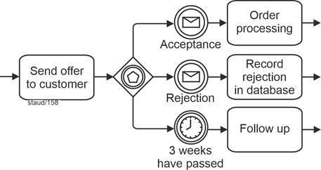
|
|
Figure 13.3-4: An event-based gateway based on message events and a timer. |
|
Elements included (selection):
- Exclusive gateway / event-based
- Message intermediate event, receiving
- Timer intermediate event / receiving
Token:
A token arrives at the gateway; depending on the message input or the time event, exactly one token is forwarded. |
|
The alternative with recipient tasks is shown in the following figure. |
|
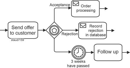
|
|
Figure 13.3-5: Event-based gateway based on recipient tasks and a timer. |
|
Elements included (selection):
- Exclusive gateway / event-based
- Receiver tasks
- Timer intermediate event / receiving |
|
13.3.2 Merging |
|
The exclusive gateway described in the previous section can be used to merge the sequence flow branches created in this way. The meaning is then the usual one: exactly one of the sequence flows must arrive at the gateway, then it continues. |
|
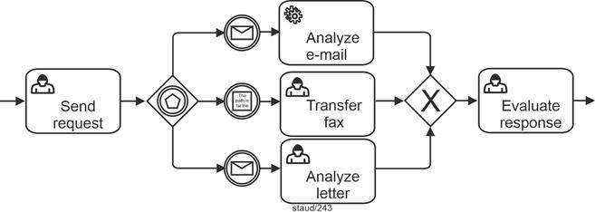
|
|
Figure 13.3-6: Event-based gateway with subsequent merging. |
|
Elements included (selection):
- Conditional intermediate event, receiving
- Service task
- Exclusive gateway / event-based
- Exclusive gateway / data-based and merging
- Message intermediate event, receiving
- User task |
|
To start |
|
If this semantics is required to start a process, a simple solution is the following, which does not explicitly represent the gateway. The events occur alternatively; it is, so to speak, an exclusive OR, so that the required semantics is realized. |
|
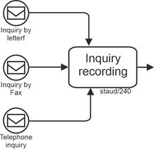
|
|
Figure 13.3-7: "Exclusive" process start by events.
Source: Derived from [OMG 2011, Figure 10.97, p. 275] |
|
Elements included (selection):
- Implicit exclusive gateway
- Message start event |
|
The disadvantage of this solution is that the gateway is not shown graphically. It is therefore not clear at first glance that these are alternative events. |
|
The more graphically meaningful solution is implemented with a merging event-based exclusive gateway for the process start. This time, however, it is not in the middle of the sequence flows, as presented above, but at the beginning of the process. |
|
The graphical symbol for this gateway is the gateway symbol, supplemented by the symbol for the event type Multiple Start Event / Top Level. See the following figure. |
|

|
|
Figure 13.3-8: Representation of an event-based exclusive gateway for the process start (multiple start event) |
|
Gateway:
- Exclusive Gateway / event-based, for process start |
|
Since business processes are very often started by alternative events, this method element is also useful. With this variant of the event-based exclusive gateway, there must be no incoming sequence flows, which is otherwise not possible with gateways. The syntax is then as follows: The first matching event starts the process. The other events of the gateway are then invalid [OMG 2011, p. 426]. |
|
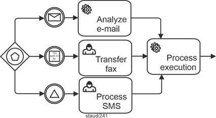
|
|
Figure 13.3-9: Representation of an event-based exclusive gateway for process start.
Source: Derived from [OMG 2011, Figure 10.98] |
|
Elements included (selection):
- Conditional intermediate event, receiving
- Service task
- Exclusive gateway / event-based, for process start
- Implicit exclusive gateway / data-based and merging
- Message intermediate event, receiving
- User task
- Signal intermediate event, receiving |
|
13.4 Parallel Gateway |
|
In business processes, multiple tasks often have to be completed in order to achieve a specific goal. Or, conversely, certain tasks must be completed before progress can be made beyond a certain point. If these are designed in such a way that they can be completed independently of each other, they can be arranged in parallel. These can be subtasks, for example. |
|
In terms of modeling, they could simply be arranged one after the other and processed sequentially. However, this would give the impression that they have to be processed one after the other. That is why they are arranged in parallel. The AND operator was created for process modeling, which is available in BPMN as a parallel gateway. |
|
Thus, in this context, "parallel" simply means that the tasks can be started and carried out independently of one another. |
|
For merging such sequence flows, the Parallel Gateway is also used. From a modeling perspective, this implies: |
|
- For outgoing sequence flows, all tasks planned after the gateway must be activated for every instance.
- For incoming sequence flows, all tasks specified before the gateway must in fact be active for every instance.
|
|
For the graphical representation, a black plus sign is added to the gateway symbol. |
|

|
|
Figure 13.4-1: Representation of a parallel gateway |
|
13.4.1 Branching |
|
Abstract example |
|
The following figure shows an abstract example. After Task1 is completed, tasks2 and Task3 are triggered. |
|
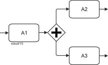
|
|
Figure 13.4-2: Parallel gateway, branching - abstract |
|
A: Activity
Gateway:
- Parallel gateway, branching
Token:
When A1 is complete, a token arrives at the gateway. There, it is duplicated. A token then starts in each of the outgoing sequence flows. |
|
Content-based example |
|
The following figure shows a content-based example. An order has been received and is created. After that, proprietary parts must be requested from the warehouse, third-party parts must be procured, and production planning must be carried out. |
|
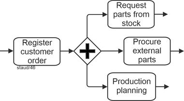
|
|
Figure 13.4-3: Parallel gateway, branching - using the example of order receipt |
|
Gateway:
- Parallel gateway, branching |
|
In this situation, according to the BPMN authors, it is also possible to dispense with the operator symbol. Here, however, the BPMN authors emphasize the uncontrolled nature of the situation, the "uncontrolled flow." In fact, this is then an implicit AND operator. |
|
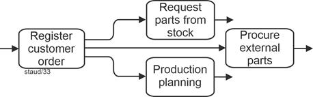
|
|
Figure 13.4-4: Order receipt - example of the use of a branching parallel gateway without a gateway symbol |
|
As a general rule, "self-explanatory" gateways should not be omitted, as this leads to confusing process models. The reader of the model must then infer the gateway situation from the semantics of the process location. |
|
The second content-based example shows a situation from a business process for processing transport orders. A transport order was received and recorded. Three tasks are then initiated, which can be completed independently of each other. |
|
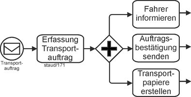
|
|
Figure 13.4-5: Start transport order with parallel gateway (branching) |
|
Elements included (selection):
- Message start event / top level
- Message start event / top level- Parallel gateway, branching |
|
13.4.2 Connecting |
|
In the connecting case, incoming parallel sequence flow branches are "synchronized" (according to the BPMN authors). Specifically, the aim is to model the following situation: All incoming edges must "arrive" before the process continues via the gateway and the next task is triggered. |
|
Abstract example |
|
Only when both tasks, Task 1 and Task 2, have been completed is Task 3 triggered. |
|
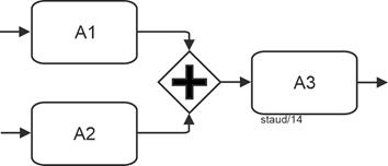
|
|
Figure 13.4-6: Abstract parallel gateway - merging |
|
A: Activity
Gateway:
- Parallel gateway, connecting
Token
Tokens arriving at the gateway wait until "all" are there, only then does it continue with a single token. |
|
Content-based example |
|
The following process fragment describes (in simplified form) the final phase of book production. Only when the book text, the index, and the current table of contents have been created can the book be sent to print. |
|
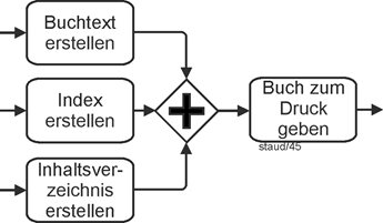
|
|
Figure 13.4-7: Final phase of book creation with parallel gateway - merging |
|
Element:
- Parallel gateway, merging |
|
The following example of production planning is similar. Once capacity has been planned and the raw materials and parts have been provided, production planning is carried out. |
|
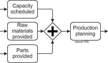
|
|
Figure 13.4-8: Production planning with parallel gateway - connecting |
|
Time window
The parallel gateway can be used to model a pattern in business processes called a time window. See [Staud 2024, section 12.6] for more information. |
|
13.5 Parallel gateway - event-based |
|
The parallel event-based gateway is used to start processes through linked events. The process only starts when all events have occurred. This corresponds to a logical AND link. |
|
The associated gateway symbol links the usual square with the event symbol Parallel Multiple for start events. |
|

|
|
Figure 13.5-1: The Parallel Event-Based Gateway for process start |
|
Gateway:
- Parallel Event Based Gateway |
|
This gateway is only available as a branching gateway. If sequence flows created by such a gateway are to be merged again, this can be done with the simple Parallel Gateway. |
|
Content-based examples |
|
The first content-based example describes the following situation: production planning requires confirmation from suppliers, confirmation of financing from the house bank, and the final order placement by the customer. Since all three are "external," communication can only take place via message traffic (see Chapter 7). Production planning only starts once all three positive messages have been received. The BPMN solution for this situation is the event-based connecting parallel gateway for process start. |
|
Since this involves messages that must all arrive, modeling with the other gateways would only be possible using auxiliary constructions. |
|
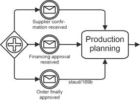
|
|
Figure 13.5-2: Process start with event-based parallel gateway - using the example Production Planning |
|
Elements included (selection):
- Implicit parallel gateway, connecting
- Message intermediate events, receiving
- Parallel event-based gateway |
|
Specifically, the following definition applies: The first event that occurs generates a new instance of the process, but the process waits for the other events to occur [OMG 2011, p. 426]. |
|
Here is a second content-based example: For a scientific conference, all incoming presentations must be reviewed by three reviewers. Only when all three have arrived is the presentation evaluated. |
|
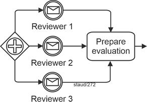
|
|
Figure 13.5-3: Process start with an event-based parallel gateway, using the example Evaluation of Presentations |
|
13.6 Inclusive Gateway |
|
In business processes, there are situations where one or more tasks must be completed before the flow can continue. This gateway corresponds to the logical OR. In terms of modeling, this means that any subset and at least one edge of the linked sequence flow branches (edges) become active in each instance of the business process. The inclusive gateway is available in BPMN to describe this situation. |
|
This gateway has the graphical form shown in the following figure. A circle or an "O" is placed in the gateway. There is another possible representation; see the abstract example below. |
|

|
|
Figure 13.6-1: Representation of an Inclusive Gateway |
|
The BPMN authors describe the structure of this gateway without resorting to the definition of the OR operator in formal languages as follows: For outgoing sequence flow branches, each individual branch is subject to an independent binary yes/no decision [OMG 2011, p. 292]. Since each path is independent, all combinations of paths are possible, including none or all. A preset continuing edge then ensures that at least one edge becomes active [ibid.], as otherwise blockages could occur in the sequence flow. |
|
Branching, abstract example |
|
The following abstract examples show the implementation, which is possible in two variants here. |
|
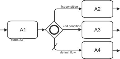
|
|
Figure 13.6-2: Inclusive gateway, branching - abstract example |
|
A: Activity
Elements included (selection):
- Inclusive gateway, branching
- Default setting for sequence flow
Token
All sequence flows that are evaluated as Yes in the independent binary Yes/No decisions receive a token. |
|
The following alternative representation of the gateway is also permitted. It uses several sequence flow branches, each marked with a small diamond at the beginning. An additional branch also specifies the default setting for the sequence flow and ensures that at least one branch becomes active. |
|
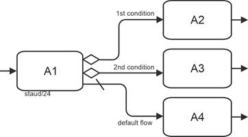
|
|
Figure 13.6-3: Inclusive gateway - abstract example (branching) with individual sequence flow branches |
|
A: Activity
Elements included (selection):
- Inclusive gateway, branching - alternative representation
- Default setting for sequence flow |
|
Digression: Process model and instances - explained in the example above. |
|
In the case of the inclusive gateway, there are many possible different instances. With three continuing branches, there are seven possibilities, since the empty set (no continuing edge) is not permitted. All possible variants are shown here for illustration purposes. The active sequence flow branches are shown in bold. |
|
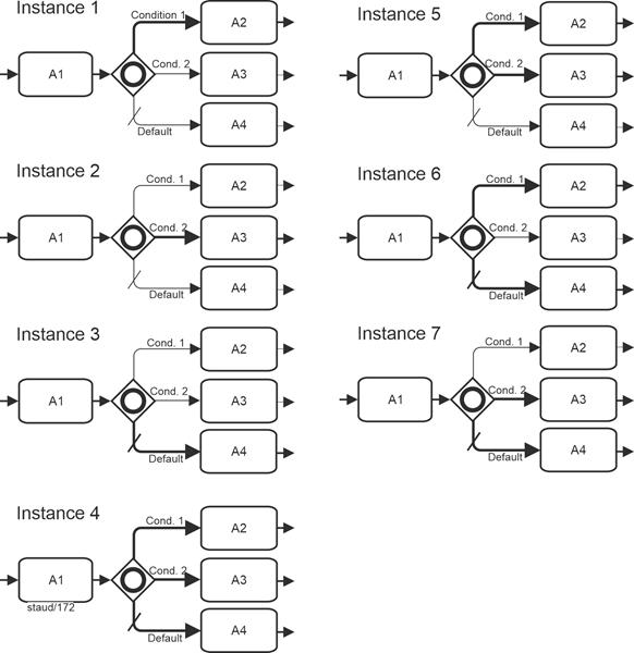
|
|
Figure 13.6-4: Process model and possible process instances - using the example of the inclusive gateway with three sequence flow branches |
|
A: Activity |
|
Content-based examples |
|
The first content-based example illustrates aspects of an incoming goods inspection. The semantics are as follows: Each of the activities can occur individually or in any combination with the others. It is also possible that no action is necessary. |
|
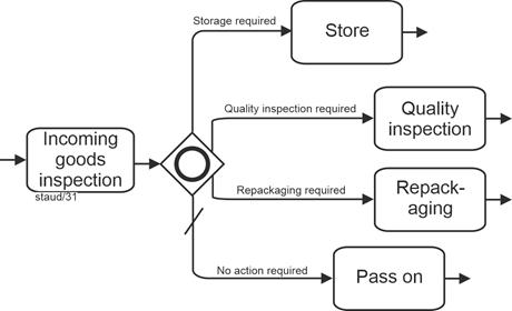
|
|
Figure 13.6-5: Inclusive gateway - using the example of an incoming goods inspection |
|
Elements included (selection):
- Inclusive gateway, branching
- Default setting for sequence flow |
|
It is easy to see that the tasks are not entirely independent of each other. For example, if no action is necessary, the other tasks cannot occur. This problem, which often arises in the practical modeling of the OR operator, is not addressed in BPMN. See [Staud 2014, section 7.3]. |
|
As a restriction, the BPMN authors state that the source object (i.e., the element preceding the operator) must not be an event. See the concept of "prohibited arrangements� in event-driven process chains, which requires the same architectural feature [Staud 2014, sections 5.4.2 and 5.4.3]. |
|
The following figure shows the alternative representation, which is also permissible. |
|
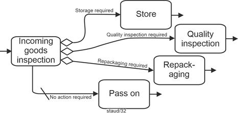
|
|
Figure 13.6-6: Representation of an Inclusive Decision with sequence flow branches |
|
Elements included (selection):
- Inclusive gateway, branching - alternative representation
- Default setting for sequence flow |
|
Merging |
|
The inclusive gateway is also used to merge sequence flow branches. The same structure as above applies to the incoming sequence flow branches, except that here it is implemented by upstream elements. This means that these sequence flow branches can occur in any combination in an instance and that at least one branch always arrives. |
|
The BPMN authors see this gateway as being used to merge a combination of alternative and parallel paths [OMG 2011, p. 292]. |
|
The following example deals with new customers of a credit institution. The excerpt shows (in simplified form) which of the services offered the new customer would like to use, as formulated, for example, in a conversation between the customer advisor and the customer. |
|
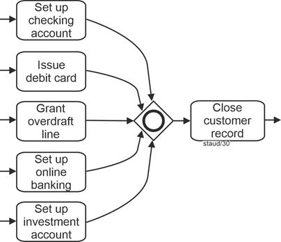
|
|
Figure 13.6-7: Customer contact at a savings bank with inclusive gateway merging |
|
Element contained (selection):
- Inclusive gateway, merging
The diagram illustrates several parallel activities performed when establishing a new customer relationship at a financial institution. After the initial onboarding, multiple services may be configured - such as setting up a checking account, issuing a debit card, granting an overdraft line, setting up online banking, or creating an investment account. Once all selected activities have been completed, the customer record is formally closed. |
|
Branching and merging |
|
The following example shows both branching and merging using the following simplified rule: A discount for attending a daycare center can be granted if at least one of the following conditions is met: The child is a sibling, the parents are unemployed, the parents are single parents. If none of these conditions are met, a rejection is formulated. |
|
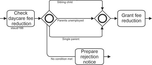
|
|
Figure 13.6-8: Checking for daycare discount with inclusive gateway |
|
Elements included (selection):
- Inclusive gateway, merging
- Inclusive gateway, branching
Continuation of the sequence flow |
|
With an inclusive gateway, several continuing sequence flow branches can occur together. This does not make continuation easy; it must be designed on the basis of the specific process semantics. Let's look at the following example. In the overall process from which this fragment originates (see the EPK version [Staud 2014, section 7.3]), the semantics are as follows: |
|
- This is a company with single-unit production.
- When a customer inquiry is received, a check is made to see whether the same system, a similar system, or components of the desired system have already been delivered, because then design and calculation documents are usually available.
- It may also turn out that nothing similar has been delivered, i.e., neither a component nor a similar or identical system.
|
|
Furthermore, the business rules in this company are as follows: |
|
- If the same system has already been delivered, with or without the delivery of components and the delivery of a similar system, the material from the same system is used as a basis and any other material that may be available is ignored.
- If a component and/or a similar system has already been delivered, the usable material is assembled and used to continue.
- If nothing similar has been delivered, the other cases are semantically impossible.
|
|
The following model fragment expresses this semantics. |
|
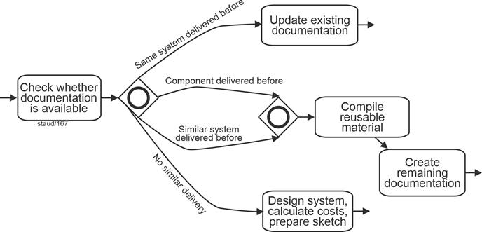
|
|
Figure 13.6-9: Request check with inclusive gateway - branching and merging |
|
Elements included (selection):
- Inclusive gateway, merging
- Inclusive gateway, branching |
|
Fuzziness |
|
This gateway expresses a process situation that is often based on a set of rules (legal or administrative) (see the example above in Figure 13.6-8), but often also on a corresponding real-world situation, as in the other examples above. In the latter case, however, the activities are often not independent of each other. For example, you can only apply for an overdraft facility if a checking account has been set up. Or there is one activity that excludes all others ("Pass on" in Fig. 13.6-6). In most cases, especially in actual analyses, these relationships are not modeled. See [Staud 2014, section 7.3] for more on the accepted ambiguity. |
|
13.7 Complex Gateway |
|
This gateway is not one of those based on logical operators. It is intended to make situations manageable that cannot be handled with the other gateways [OMG 2011, section 10.5.5]. The BPMN authors write that this gateway is intended to help |
|
"... to model complex synchronization behavior, in particular race situations" [OMG 2011, pp. 295, 437]. |
|
Race situations
Suppose that 10 suppliers are contacted and asked to submit bids as part of a tender process. The business rule could then be that the selection process begins once the first 5 responses have been received and the supplier is selected. Since the suppliers are, so to speak, in a race situation, the BPMN authors refer to this as a "race situation." |
|
This gateway is represented by a star inserted in the middle of the gateway symbol, as shown in the following figure. |
|

|
|
Figure 13.7-1: Representation of a complex gateway |
|
To understand this gateway, it is essential to consider its internal structure. First, the attributes: |
|
- The "gates" at which the sequence flows (tokens) arrive have an attribute (data type integer) called activationCount. The value of this attribute indicates how many tokens are currently on the incoming sequence flows, i.e., how many sequence flows are queued at the gateway.
- The gateway itself has an attribute called activationExpression (Boolean), which refers to the data at this process point and to the activationCount attribute. For example, with m incoming sequence flows (x1 ... xm), the expression xl+x2+...+xm >= 3 could be used if you want 3 of m incoming tokens to be necessary to get to a subsequent token [OMG 2011, p. 437].
- The variable activationCount should only be used in expressions of the form expr >= const with an arithmetic expression for expr that only uses addition and with const as an expression that remains constant throughout the process.
|
|
Then the states. A complex gateway has one internal state: |
|
- waitingForStart or
- waitingForReset (meaning: waitingForStart=false)
|
|
The gateway is always in one of these states, starting in waitingForStart. The activationExpression attribute is checked when the first token appears on an incoming sequence flow. If the check returns "true," a token is consumed from each incoming sequence flow (which then has a token). |
|
To continue the process via the gateway, the conditions of all outgoing sequence flows are checked. |
|
Each outgoing sequence flow is subject to a Boolean condition that determines whether the sequence flow becomes active (receives a token) or not. This condition can use the state of the gateway. Those outgoing sequence flows whose conditions are met receive a token. If none are true, the default sequence flow is used. If there is no default sequence flow, an exception event is triggered. |
|
This completes the first phase. The gateway then changes its status to waiting for reset. It now waits for tokens from all sequence flows that did not receive a token in the first phase, unless none are expected. |
|
If a restart (reset) occurs, the gateway consumes one token from each incoming sequence flow if it has a token (i.e., it was not consumed in the first phase). It then checks all conditions on the outgoing sequence flows to determine which one receives a token. Only those whose check returns true receive one. If no check returns true, the default sequence flow receives a token. The gateway then changes its state back to waitingForStart. |
Restart |
With the above description, the preparation for implementation - whether in terms of programming or execution by a business process engine - is already clarified to some extent. The concept therefore aims at the automated execution of processes, not at as-is analyses. |
|
13.7.1 Branching |
|
Abstract example |
|
The following example also serves to illustrate the above explanations. There are m sequence flows at the gateway, which are evaluated as described, and n sequence flows and one preset sequence flow depart. Which ones depart depends on the evaluations at the gateway. |
|
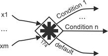
|
|
Figure 13.7-2: Merging and branching of sequence flows with a complex gateway
Source: [OMG 2011, Figure 13.7, p. 437] |
|
Elements included (selection):
- Complex gateway
- Merging and branching sequence flows with a complex gateway |
|
Content-based example |
|
There are indeed situations in business processes that cannot be mapped using standard operators or gateways, or can only be mapped with great difficulty and by accepting syntactically complex constructions. For such cases, BPMN provides the Complex Gateway. The following example deals with a regularly automated inventory check. Depending on the result of the check (simplified here), further activities are carried out. |
|
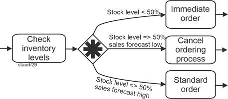
|
|
Figure 13.7-3: Inventory check with a complex gateway |
|
Gateway:
- Complex gateway, branching |
|
13.7.2 Merging |
|
Abstract example |
|
Here is an abstract representation of such a process situation: A1, A2, and A3 are implemented in a certain way, then it continues to A4. |
|
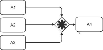
|
|
Figure 13.7-4: Merging complex gateway - abstract |
|
A: Activity
Gateway:
- Complex gateway, connecting |
|
Content-based example |
|
The following model fragment describes the situation in which numerous offers are requested from potential suppliers. The business rule is that the evaluation of the offers begins when three have been received. |
|
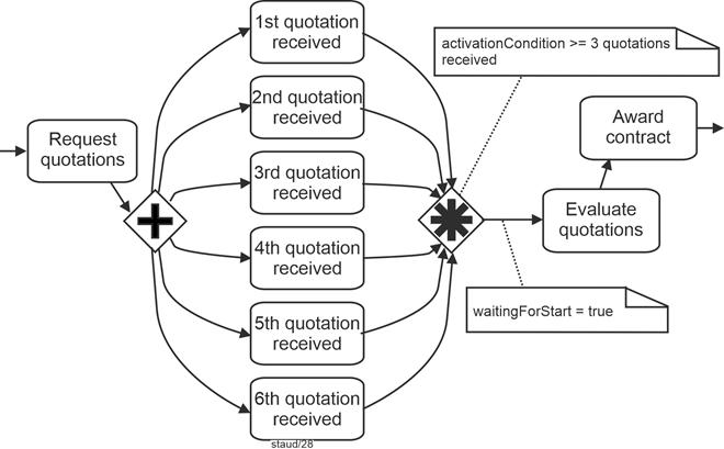
|
|
Figure 13.7-5: Offer review and award with a connecting complex gateway (race situation) |
|
Elements included (selection):
- Complex gateway, merging
- Parallel gateway, branching
- Race situation
- Attributes of the complex gateway |
|
|
|
This concludes the introduction to BPMN gateways. The following figure provides an overview. |
|
|
|
BPMN gateways |
|
| BPMN designation |
Logical operator |
Gateway symbol(s) |
| Exclusive gateway, data-based
(branching and merging) Allows decision situations to be captured "from within the process." A sequence flow becomes active/must arrive. |
XOR |
 
|
| Exclusive gateway,
event-based (branching) Allows decision situations to be captured by events (message arrival). A sequence flow becomes active/must arrive. |
XOR |
 
|
| Parallel Gateway
(branching and merging)
Parallel means that the tasks are started and processed independently of each other. However, all of them must be started or arrive in order for "things to continue." |
AND |

|
| Parallel Event-Based Gateway
(branching)
Used to start processes through events that are linked with the logical AND. All must be started for "things to get going." |
AND |

|
| Inclusive Gateway
(branching and merging)
Used for branching and merging based on the logical OR ("any subset of branches may be taken") |
OR |

|
| Complex Gateway
(branching and merging)
Does not rely on logical operators. It is intended to make situations manageable that cannot be handled with the other gateways ("... to model complex synchronization behavior" [OMG 2011, p. 295]). |
--- |

|
| |
13.8 Control flow through compensation |
|
The modeling element of compensation (see also [Staud 2024, section 9.2]) is not a gateway, at least not at first glance. The activities resulting from compensation (compensation handler, see below) are also not part of the normal flow (see below) and therefore must not be instantiated when the process itself is instantiated. However, because a compensation represents a branching into a sequence of actions that also triggers activities, it is included in this chapter. |
|
Compensation describes the reversal of work steps that have already been successfully completed because their results and possible side effects are no longer desired. This is only possible once the activity has been completed. If an activity is still active, it cannot be compensated, only canceled. |
|
As seen above, there are four variants of compensation events: a start event, a sending and receiving intermediate event, and an end event. |
|
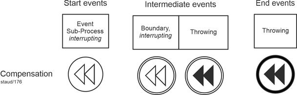
|
|
Figure 13.8-1: Events for branching to compensation activities |
|
Cf. Figure 13.8-3 as well as [Staud 2024, Figure 14.3-1] for numerous examples of this event type. |
|
The first element (from the left) is used when subprocesses are to be started. It is only used for embedded compensation subprocesses and becomes active when compensation is pending. |
|
The second element (intermediate event / interrupting boundary line) is placed on the edge of an activity that is located in the middle of the process and can receive messages to start the compensation execution. It therefore receives the compensation event that arises in the activity. Receiving compensation intermediate events may only be placed on the boundary line of activities and not in the normal flow. |
|
The third element in the normal flow indicates that compensation is necessary. It therefore triggers a compensation event. The sequence is then as follows: When an activity is identified and successfully completed, it is reversed. Of course, the activity must be "visible" to the compensation intermediate event (see below), i.e., it must be able to perceive the event. |
|
The fourth element is a final event. It signals that compensation is necessary with regard to an activity. It can be used in any subprocess or process. Either in the normal flow at the same level as the subprocess or in a compensation subprocess contained in the subprocess that contains an activity. If no associated activity can be identified, all successfully completed activities that are visible to the compensation end event are compensated in reverse order. |
|
Visibility |
|
An activity is visible to a compensation (intermediate/end) event if it is contained in the normal flow at the same subprocess level or if it is located in an associated event subprocess. [OMG 2011, p. 248] |
|
What does compensation involve overall? |
|
Compensation requires the following elements: |
|
- One or more activities that may need to be reversed.
- A compensation handler that performs the necessary steps if required.
- A connection between the activity and the compensation activities.
|
|
The so-called compensation handler represents a set of activities that are not linked to other parts of the BPMN model. It is triggered by a receiving compensation event. This is either located graphically on the boundary line of the activity ("boundary event") or, in the case of a compensation subprocess, the start event of the compensation handler. |
|
Compensation is therefore triggered by a compensation event that has been issued. A second possibility is that it is triggered recursively by another compensation handler. |
|
Graphical representation of the connection between activity and compensation activities |
|
If the connection is made by an event on the boundary line ("boundary event"), it is represented as shown in the following figure. This includes a compensation activity that is connected to the "boundary event" by means of an association. |
|
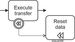
|
|
Figure 13.8-2: Compensation with event trigger on boundary |
|
Elements included (selection):
- Compensation intermediate event / boundary, interrupting
- Compensation task |
|
The connection can also be established via a compensation event subprocess. This must be contained in a process or subprocess. Like the "boundary line events," it is also outside the normal flow, but can access the data of the parent process. |
|
The following figure shows the graphical implementation. The compensation subprocess is highlighted by a dotted line. The parent subprocess Bookings comprises the various booking processes with the compensation intermediate events on the boundary lines of the actual activities. The subprocess contains a compensation subprocess. |
|
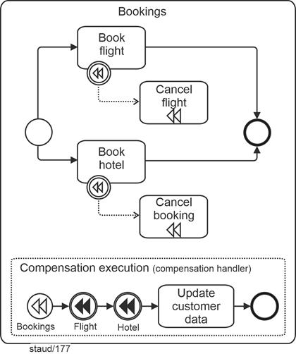
|
|
Figure 13.8-3: Flight and hotel booking, with compensation subprocess.
Source: [OMG 2011, p. 303, Figure 10.122], slightly modified. |
|
Elements included (selection):
- Compensation task
- Compensation start event / event subprocess, interrupting
- Compensation event subprocess (unfolded)
- Compensation intermediate event / sending
- Compensation intermediate event / boundary line, interrupting
Variants of this business process can be found in [Staud 2024]:
Figure 10.8-1 (variant 1), Figure 10.9-3 (variant 2), Figure 11.8-3 (variant 3), Figure 14.3-1 (variant 4), and Figure 14.4-1 (variant 5) |
|
A compensation handler is either user-defined or implicit. The implicit compensation handler of a subprocess calls all compensation handlers of its enclosed activities in reverse order (according to sequence flow) [OMG 2011, p. 235]. |
|
Finally, a remark on the distinction between normal and non-normal sequence flows. |
|
Normal flow and non-normal flow |
|
The BPMN authors distinguish between normal and non-normal flow. Normal flow is the flow created by sequence flows. All others are, so to speak, non-normal. These include flows related to compensations (from the "boundary event" to the compensation activity) or to the compensation subprocess. Accordingly, there are model elements that are allowed in non-normal flow but not in normal flow. For example, the flows surrounding compensation. Another reason for this distinction is that non-normal flows are not activated when the business process is instantiated. |
|
14 References |
|
A comprehensive list of publications in the field of process modeling can be found here: |
|
https://www.staud.info/litohneFr/li_t_1.php |
|
|
|
Becker, Kugeler und Rosemann 2012 (Hrsg.)
Becker, Jörg; Kugeler, Martin; Rosemann, Michael (Hrsg.): Prozessmanagement. Ein Leitfaden zur prozessorientierten Organisationsgestaltung (7. Aufl.), Berlin u.a. 2012 |
|
Bullinger und Fähnrich 1997
Bullinger, Hans-Jörg; Fähnrich, Klaus-Peter: Betriebliche Informationssysteme. Grundlagen und Werkzeuge der methodischen Softwareentwicklung. Berlin u.a. 1997 |
|
Keller, Nüttgens und Scheer 1992
Keller, G.; Nüttgens, M.; Scheer, A.-W.: Semantische Prozessmodellierung auf der Grundlage Ereignisgesteuerter Prozessketten, Veröffentlichungen des Instituts für Wirtschaftsinformatik (Iwi), Universität des Saarlandes, Heft 89, Januar 1992 |
|
Mertens 2013
Mertens, Peter: Integrierte Informationsverarbeitung 1. Operative Systeme in der Industrie (18. Auflage), Wiesbaden 2013 (Springer Gabler) |
|
Österle 1995
Österle, Hubert: Business Engineering. Prozess- und Systementwicklung. Band 1: Entwurfstechniken, Berlin u.a. 1995 |
|
OMG 2003 Object Management Group: UML 2.0 Superstructure Specification (Unified Modeling Language: Superstructure, version 2.0, final Adopted Specification, ptc/03-08-02), August 2003 |
|
OMG 2009 Object Management Group (OMG): Business Process Modeling Notation (BPMN). Version 1.2 January 2009 (OMG Document Number: formal/2009-01-03. Standard document URL: http://www.omg.org/spec/BPMN/1.2) |
|
OMG 2011 Object Management Group (OMG): Business Process Modeling Notation (BPMN). Version 2.0 January 2011 (OMG Document Number: formal/2011-01-03. Standard document URL: http://www.omg.org/spec/BPMN/2.0) |
|
OMG 2013 Object Management Group (OMG): Business Process Model and Notation (BPMN). Version 2.0.2 January 2011 (OMG Document Number: formal/2011-01-03. Standard document URL: https://www.omg.org/spec/BPMN/2.0.2/About-BPMN/) |
|
Scheer 1996
Scheer, August-Wilhelm: Business Process Engineering. Reference Models for Industrial Entreprises. (2. Auflage), Berlin u.a.1996 |
|
Scheer 1997
Scheer, August-Wilhelm: Wirtschaftsinformatik. Referenzmodelle für industrielle Geschäftsprozesse (7. Auflage), Berlin u.a. 1997 |
|
Scheer 1998
Scheer, August-Wilhelm: Wirtschaftsinformatik. Studienausgabe. Referenzmodelle für industrielle Geschäftsprozesse (2. Aufl.), Berlin u.a. 1998 |
|
Scheer 1998a
Scheer, August-Wilhelm: ARIS - vom Geschäftsprozess zum Anwendungssystem (3. Auflage), Berlin u.a.1998 |
|
Scheer 1998b
Scheer, August-Wilhelm: ARIS - Modellierungsmethoden, Metamodelle, Anwendungen (3. Auflage), Berlin u.a.1998 |
|
Scheer 1998c
Scheer, August-Wilhelm: Wirtschaftsinformatik. Studienausgabe. Referenzmodelle für industrielle Geschäftsprozesse (2. Auflage), Berlin u.a. 1998 (Springer) |
|
Scheer 1999
Scheer, August-Wilhelm: ARIS, Business Process Frameworks. (3. Auflage), Berlin u.a.1999 |
|
Scheer 2000
Scheer, August-Wilhelm: ARIS, Business Process Modeling. (3. Aufl.), Berlin u.a. 2000 |
|
Scheer 2020
Scheer, August-Wilhelm: Unternehmung 4.0. Vom disruptiven Geschäftsmodell zur Automatisierung der Geschäftsprozesse, 3. Auflage, Wiesbaden 2020 |
|
Schmelzer und Sesselmann 2013
Schmelzer, Hermann J.; Sesselmann, Wolfgang: Geschäftsprozessmanagement in der Praxis. Kunden zufriedenstellen, Produktivität steigern, Wert erhöhen (8. Auflage). München 2013. |
|
Staud 2006 Staud, Josef Ludwig: Geschäftsprozessanalyse. Ereignisgesteuerte Prozessketten und objektorientierte Geschäftsprozessmodellierung für Betriebswirtschaftliche Standardsoftware (3. Auflage). Berlin u.a. 2006 |
|
Staud 2014 Staud, Josef Ludwig: Ereignisgesteuerte Prozessketten. Das Werkzeug für die Modellierung von Geschäftsprozessen. Vilshofen 2014. |
|
Staud 2019 Staud, Josef Ludwig: Unternehmensmodellierung - Objektorientierte Theorie und Praxis mit UML 2.5. (2. Auflage). Berlin u.a. 2019 (Springer Gabler) |
|
Staud 2024 Staud, Josef Ludwig: Geschäftsprozesse und ihre Modellierung mit der Methode Business Procass Model and Notation (BPMN 2.0). (2. Auflage). Hamburg 2024 (tredition) |
|
Staud 2025
Staud, Josef Ludwig: Ereignisgesteuerte Prozessketten. Das Werkzeug für die Modellierung von Geschäftsprozessen (2. Auflage). Hamburg 2025 (tredition) |
|
|
|
|
|
|